OMNICOMP GRAPHICS CORPORATION
M&M BASIC
|
Category |
Video |
|
Video Types Supported |
VGA |
|
Video Processor |
S2C9001 |
|
Highest Resolution Supported |
720 x 480 |
|
Data Bus Type |
16-bit ISA |
|
Memory Type |
N/A |
|
Maximum Onboard Memory |
N/A |
|
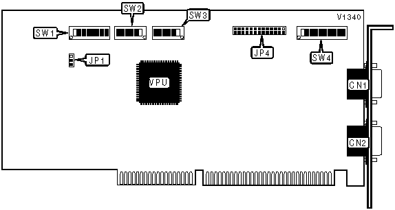
CONNECTIONS | |||
|
Purpose |
Location |
Purpose |
Location |
|
Video input connector |
CN1 |
VESA feature connector |
JP4 |
|
Video output connector |
CN2 | ||
|
I/O REGISTER SPACE CONFIGURATION | ||
|
Setting |
JP1 | |
| » |
Fixed |
Pins 1 & 2 closed |
|
Programmed |
Pins 2 & 3 closed | |
|
BASE I/O ADDRESS SELECTION | ||||||||
|
Address |
SW1/1 |
SW1/2 |
SW1/3 |
SW1/4 |
SW1/5 |
SW1/6 |
SW1/7 |
SW1/8 |
|
100h |
Off |
On |
On |
On |
On |
On |
On |
On |
|
200h |
On |
Off |
On |
On |
On |
On |
On |
On |
|
300h |
Off |
Off |
On |
On |
On |
On |
On |
On |
|
400h |
On |
On |
Off |
On |
On |
On |
On |
On |
|
500h |
Off |
On |
Off |
On |
On |
On |
On |
On |
|
FB00h |
Off |
Off |
On |
Off |
Off |
Off |
Off |
Off |
|
FC00h |
On |
On |
Off |
Off |
Off |
Off |
Off |
Off |
|
FD00h |
Off |
On |
Off |
Off |
Off |
Off |
Off |
Off |
|
FE00h |
On |
Off |
Off |
Off |
Off |
Off |
Off |
Off |
|
FF00h |
Off |
Off |
Off |
Off |
Off |
Off |
Off |
Off |
|
Note: A total of 255 base address settings are available. The switches are a binary representation of the decimal memory addresses. SW1/8 is the Most Significant Bit and switch SW1/1 is the Least Significant Bit. The switches have the following decimal values: SW1/8=32768, SW1/7=16384, SW1/6=8192, SW1/5=4096, SW1/4=2048, SW1/3=1024, SW1/2=512, SW1/1=256. Turn off the switches and add the values of the switches that are off to obtain the correct memory address. (Off=1, On=0) | ||||||||
|
VIDEO INPUT IMPEDANCE SELECTION | |||
|
Setting |
SW4/2 |
SW4/3 |
SW4/4 |
|
Red display signal from VGA card |
Off |
Off |
Off |
|
Green display signal from VGA card |
Off |
Off |
Off |
|
Blue display signal from VGA card |
Off |
Off |
Off |
|
Channel 1 composite video or Y of S-video |
Off |
Off |
Off |
|
Channel 2 composite video or Y of S-video |
Off |
Off |
Off |
|
Channel 3 composite video or Y of S-video |
Off |
Off |
Off |
|
Channel 1 C of S-video |
Off |
Off |
On |
|
Channel 2 C of S-video |
Off |
On |
Off |
|
Channel 3 C of S-video |
On |
Off |
Off |
|
VIDEO INPUT IMPEDANCE SELECTION (CON’T) | |||
|
Setting |
SW4/5 |
SW4/6 |
SW4/7 |
|
Red display signal from VGA card |
Off |
Off |
Off |
|
Green display signal from VGA card |
Off |
Off |
Off |
|
Blue display signal from VGA card |
Off |
Off |
Off |
|
Channel 1 composite video or Y of S-video |
Off |
Off |
On |
|
Channel 2 composite video or Y of S-video |
Off |
On |
Off |
|
Channel 3 composite video or Y of S-video |
On |
Off |
Off |
|
Channel 1 C of S-video |
Off |
Off |
Off |
|
Channel 2 C of S-video |
Off |
Off |
Off |
|
Channel 3 C of S-video |
Off |
Off |
Off |
|
VIDEO INPUT IMPEDANCE SELECTION (CON’T) | |||
|
Setting |
SW4/8 |
SW4/9 |
SW4/10 |
|
Red display signal from VGA card |
Off |
Off |
On |
|
Green display signal from VGA card |
Off |
On |
Off |
|
Blue display signal from VGA card |
On |
Off |
Off |
|
Channel 1 composite video or Y of S-video |
Off |
Off |
Off |
|
Channel 2 composite video or Y of S-video |
Off |
Off |
Off |
|
Channel 3 composite video or Y of S-video |
Off |
Off |
Off |
|
Channel 1 C of S-video |
Off |
Off |
Off |
|
Channel 2 C of S-video |
Off |
Off |
Off |
|
Channel 3 C of S-video |
Off |
Off |
Off |
|
MISCELLANEOUS TECHNICAL NOTE |
|
SW2 is the Video Color Switch. It is used to adjust the timing of the color information in the video signal. SW2 consists of six switches the default is the SW2/4 switch in the On position, & the rest of the switches in the Off position. You must use a "trial and error" process to adjust SW2. Only one switch can be On at any given time. |
|
MISCELLANEOUS TECHNICAL NOTE |
|
SW3 is the Color Key Skew Switch. It is used to adjust the timing of the color key signal. SW3 consists of six switches the default is the SW3/4 switch in the On position, & the rest of the switches in the Off position. You must use a "trial and error" process to adjust SW3. Only one switch can be On at any given time. |
|
FACTORY CONFIGURED - DO NOT ALTER | |
|
Switch |
Position |
|
SW4/1 |
On |