MICROCOM, INC.
DESKPORTE FAST
|
Card Type |
Modem (synchronous/asynchronous) |
|
Processor |
Z80182 |
|
Processor Speed |
18.4MHz |
|
Chipset |
Microcom |
|
Maximum Onboard Memory |
64KB SRAM (32KB battery backup)/128KB Flash ROM |
|
Maximum Data Rate |
28.8Kbps |
|
Maximum Fax Rate |
14.4Kbps |
|
Data Bus |
Serial, parallel |
|
Fax Class |
Class I |
|
Data Modulation |
Bell 103A/212A ITU-T V.21, V.22, V.23, V.22bis, V.32, V.32bis Rockwell V.FC |
|
Fax Modulation |
Unidentified |
|
Error Correction/Compression |
MNP5, MNP10, V.42, V.42bis |
|
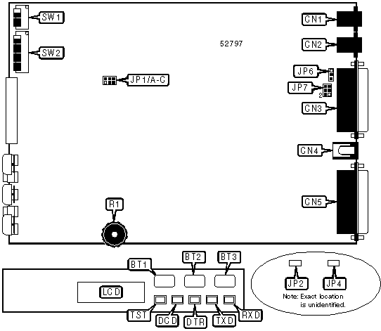
CONNECTIONS | ||||||
|
Function |
Label |
Function |
Label | |||
|
Talk/Data button |
BT1 |
RS-232/422 port |
CN3 | |||
|
Originate/Answer button |
BT2 |
DC power |
CN4 | |||
|
Power switch |
BT3 |
Parallel port |
CN5 | |||
|
Line in |
CN1 |
LCD display |
LCD | |||
|
Line out |
CN2 |
Volume |
R1 | |||
|
USER CONFIGURABLE SETTINGS | ||
|
Setting |
Label |
Position |
|
í Factory configured - do not alter |
JP2 |
Unidentified |
|
í Factory configured - do not alter |
JP4 |
Unidentified |
|
í Pin 1 of serial port connected to signal ground |
JP6 |
Pins 2 & 3 closed |
|
Pin 1 of serial port connected to chassis ground |
JP6 |
Pins 1 & 2 closed |
|
í Received signal level set to -43 dBm |
JP7 |
Pins 1 & 2 closed |
|
Received signal level set to -33 dBm |
JP7 |
Pins 2 & 3 closed |
|
LINE TYPE SELECTION | |||
|
Setting |
JP1/A |
JP1/B |
JP1/C |
|
Leased line (0 dBm) |
Open |
Open |
Closed |
|
Permissive (-10 dBm) |
Closed |
Open |
Open |
|
Programmable (-12 dBm) |
Open |
Closed |
Open |
|
CONFIGURATION MODE FUNCTION | |
|
Mode |
Function |
|
0 |
Normal operation of modem - sets power-up defaults for various commands |
|
1 |
Controls flow control and connect mode defaults |
|
2 |
Selects leased-line and synchronous mode options |
|
3 |
Controls serial port signals |
|
4 |
Controls synchronous clock and busy out |
|
5 |
Selects echo and result code formatting |
|
6 |
Controls various command options |
|
7 |
Selects flow control and parity checking |
|
8 |
Controls serial port parity and speed |
|
9 |
Configures line speed options |
|
10 |
Performs diagnostic tests |
Note: The DeskPorte FAST modem can be configured by switches in eleven modes, although command configuration is preferable when possible. Configuration modes 1 through 9 can be stored in NVRAM by pressing the reset switch. Mode 0 is read on reset or power-up is SW2/5 is on. If SW2/5 is off, no switch settings will be used. Before operating, the modem’s switches should be returned to mode 0 and the appropriate settings made. | |
|
CONFIGURATION MODE SELECTION | ||||
|
Setting |
SW1/1 |
SW1/2 |
SW1/3 |
SW1/4 |
|
í 0 |
Off |
Off |
Off |
Off |
|
1 |
On |
Off |
Off |
Off |
|
2 |
Off |
On |
Off |
Off |
|
3 |
On |
On |
Off |
Off |
|
4 |
Off |
Off |
On |
Off |
|
5 |
On |
Off |
On |
Off |
|
6 |
Off |
On |
On |
Off |
|
7 |
On |
On |
On |
Off |
|
8 |
Off |
Off |
Off |
On |
|
9 |
On |
Off |
Off |
On |
|
10 |
On |
On |
On |
On |
Configuration Mode 0 - Normal Operation
|
USER CONFIGURABLE SETTINGS | ||
|
Setting |
Label |
Position |
|
í Factory configured - do not alter |
SW2/3 |
Off |
|
í Modem reloads user configuration on reset |
SW2/4 |
Off |
|
Modem reloads factory configuration on reset |
SW2/4 |
On |
|
í Modem does not load configuration from switches |
SW2/5 |
Off |
|
Modem loads configuration from switches |
SW2/5 |
On |
|
í Cellular phone support disabled |
SW2/6 |
Off |
|
Cellular phone support enabled |
SW2/6 |
On |
|
í Command set enabled |
SW2/7 |
Off |
|
Command set disabled |
SW2/7 |
On |
|
í Auto-answer enabled |
SW2/8 |
Off |
|
Auto-answer disabled |
SW2/8 |
On |
|
COMMAND SET SELECTION | ||
|
Setting |
SW2/1 |
SW2/2 |
|
Asynchronous AT |
Off |
Off |
|
Asynchronous V.25bis |
On |
Off |
|
Synchronous V.25bis |
Off |
On |
|
Transparent synchronous, command set disabled |
On |
On |
Configuration Mode 1 - Flow Control/Connect Mode
|
USER CONFIGURABLE SETTINGS | ||
|
Setting |
Label |
Position |
|
í Factory configured - do not alter |
SW2/6 |
N/A |
|
í Factory configured - do not alter |
SW2/7 |
N/A |
|
í Factory configured - do not alter |
SW2/8 |
N/A |
|
FLOW CONTROL SELECTION | ||
|
Setting |
SW2/1 |
SW2/2 |
|
í Use setting from command set |
Off |
Off |
|
Flow control disabled |
On |
Off |
|
Use bidirectional XON/XOFF |
Off |
On |
|
Use unidirectional XON/XOFF |
On |
On |
|
CONNECT MODE SELECTION | |||
|
Setting |
SW2/3 |
SW2/4 |
SW2/5 |
|
í Use setting from command set |
Off |
Off |
Off |
|
Normal mode |
On |
Off |
Off |
|
Direct mode |
Off |
On |
Off |
|
Reliable mode |
On |
On |
Off |
|
Auto-reliable mode |
Off |
Off |
On |
|
LAPM reliable mode |
On |
Off |
On |
|
LAPM auto-reliable mode |
Off |
On |
On |
|
LAPM and MNP reliable mode |
On |
On |
On |
Configuration Mode 2 - Leased-Line/Synchronous
|
USER CONFIGURABLE SETTINGS | ||
|
Setting |
Label |
Position |
|
í Factory configured - do not alter |
SW2/8 |
N/A |
|
SYNCHRONOUS AUTO-DIAL CONFIGURATION | ||
|
Setting |
SW2/1 |
SW2/2 |
|
í Use setting from command set |
Off |
Off |
|
Manual dial only |
On |
Off |
|
Dial first stored number |
Off |
On |
|
Dial second stored number |
On |
On |
|
LINE TYPE SELECTION | |||
|
Setting |
SW2/3 |
SW2/4 |
SW2/5 |
|
í Use setting from command set |
Off |
Off |
Off |
|
Switched line type |
On |
Off |
Off |
|
Leased line type |
Off |
On |
Off |
|
Leased line type, modem will go off hook for 6 seconds when Originate/Answer button pushed |
On |
On |
Off |
|
SYNCHRONOUS MODE CTS SIGNAL CONFIGURATION | ||
|
Setting |
SW2/6 |
SW2/7 |
|
í Use setting from command set |
Off |
Off |
|
CTS follows RTS |
On |
Off |
|
CTS forced high |
Off |
On |
|
CTS and RTS emulate half-duplex connection |
On |
On |
Configuration Mode 3 - Serial Port Signals
|
CD SIGNAL CONFIGURATION | ||
|
Setting |
SW2/1 |
SW2/2 |
|
í Use setting from command set |
Off |
Off |
|
CD forced high |
On |
Off |
|
CD normal |
Off |
On |
|
CD forced high except at disconnect |
On |
On |
|
DSR AND CTS SIGNAL CONFIGURATION | |||
|
Setting |
SW2/3 |
SW2/4 |
SW2/5 |
|
í Use setting from command set |
Off |
Off |
Off |
|
DSR and CTS forced high |
On |
Off |
Off |
|
CTS follows CD; if &C is not set to 1 then DSR also follows CD, otherwise it follows OH |
Off |
On |
Off |
|
DSR and CTS follow CD |
On |
On |
Off |
|
DSR normal, CTS forced high |
Off |
Off |
On |
|
DSR and CTS normal |
On |
Off |
On |
|
DTR SIGNAL CONFIGURATION | |||
|
Setting |
SW2/6 |
SW2/7 |
SW2/8 |
|
í Use setting from command set |
Off |
Off |
Off |
|
DTR ignored |
On |
Off |
Off |
|
Modem enters command state on low DTR |
Off |
On |
Off |
|
Modem goes on hook on low DTR |
On |
On |
Off |
|
Modem resets on low DTR |
Off |
Off |
On |
Configuration Mode 4 - Clock Source/Busy Out
|
USER CONFIGURABLE SETTINGS | ||
|
Setting |
Label |
Position |
|
í Factory configured - do not alter |
SW2/5 |
N/A |
|
í Factory configured - do not alter |
SW2/6 |
N/A |
|
í Factory configured - do not alter |
SW2/7 |
N/A |
|
í Factory configured - do not alter |
SW2/8 |
N/A |
|
LOOPBACK TEST AND BUSY OUT CONFIGURATION | ||
|
Setting |
SW2/1 |
SW2/2 |
|
í Use setting from command set |
Off |
Off |
|
Pins 18 and 21 have no function |
On |
Off |
|
Busy Out when pin 18 is high, perform local analog loopback test on high DTR |
Off |
On |
|
Perform local analog loopback test when pin 18 is high, remote digital loopback test when pin 21 is high |
On |
On |
|
CLOCK SOURCE SELECTION | ||
|
Setting |
SW2/3 |
SW2/4 |
|
í Use setting from command set |
Off |
Off |
|
Internal clock source |
On |
Off |
|
External clock source |
Off |
On |
|
Slave to remote clock |
On |
On |
Configuration Mode 5 - Echo/Result Codes
|
USER CONFIGURABLE SETTINGS | ||
|
Setting |
Label |
Position |
|
í Factory configured - do not alter |
SW2/7 |
N/A |
|
í Factory configured - do not alter |
SW2/8 |
N/A |
|
COMMAND ECHO CONFIGURATION | ||
|
Setting |
SW2/1 |
SW2/2 |
|
í Use setting from command set |
Off |
Off |
|
Command echo disabled |
On |
Off |
|
Command echo enabled |
Off |
On |
|
RESULT CODE CONFIGURATION | ||
|
Setting |
SW2/3 |
SW2/4 |
|
í Use setting from command set |
Off |
Off |
|
Result codes enabled |
On |
Off |
|
Result codes disabled |
Off |
On |
|
Result codes enabled on originate only |
On |
On |
|
RESULT CODE TYPE SELECTION | ||
|
Setting |
SW2/5 |
SW2/6 |
|
í Use setting from command set |
Off |
Off |
|
Modem will send verbose result codes |
On |
Off |
|
Modem will send numeric result codes |
On |
On |
Configuration Mode 6 - Various
|
ERROR CORRECTION RESULT CODE CONFIGURATION | ||
|
Setting |
SW2/1 |
SW2/2 |
|
í Use setting from command set |
Off |
Off |
|
Use standard format |
On |
Off |
|
Use error correction result codes with 9600 given for all speeds between 4800bps and 12Kbps |
Off |
On |
|
Use error correction result codes with real speed given |
On |
On |
|
SERIAL PORT SPEED LOCK SELECTION | ||
|
Setting |
SW2/3 |
SW2/4 |
|
í Use setting from command set |
Off |
Off |
|
Serial port speed locked |
On |
Off |
|
Serial port speed follows connect speed |
On |
On |
|
BREAK TYPE | ||
|
Setting |
SW2/5 |
SW2/6 |
|
í Use setting from command set |
Off |
Off |
|
Use setting for \K0 |
On |
Off |
|
Use setting for \K1 |
Off |
On |
|
Use setting for \K5 |
On |
On |
|
INACTIVITY TIMER | ||
|
Setting |
SW2/7 |
SW2/8 |
|
í Use setting from command set |
Off |
Off |
|
Inactivity timer disabled |
On |
Off |
|
Set inactivity timer to 2 minutes |
Off |
On |
|
Set inactivity timer to 15 minutes |
On |
On |
Configuration Mode 7 - Flow Control/Parity Checking
|
USER CONFIGURABLE SETTINGS | ||
|
Setting |
Label |
Position |
|
í Factory configured - do not alter |
SW2/6 |
N/A |
|
í Factory configured - do not alter |
SW2/7 |
N/A |
|
í Factory configured - do not alter |
SW2/8 |
N/A |
|
FLOW CONTROL | |||
|
Setting |
SW2/1 |
SW2/2 |
SW2/3 |
|
í Use setting from command set |
Off |
Off |
Off |
|
Flow control disabled |
On |
Off |
Off |
|
Bidirectional XON/XOFF flow control enabled |
Off |
On |
Off |
|
CTS flow control by DCE enabled |
On |
On |
Off |
|
Bidirectional RTS/CTS flow control enabled |
Off |
Off |
On |
|
Unidirectional XON/XOFF flow control by DCE enabled |
On |
Off |
On |
|
CTS forced low until connection then CTS flow control by DCE |
Off |
On |
On |
|
Bidirectional RTS/CTS flow control after connection |
On |
On |
On |
|
ESCAPE AND FLOW CONTROL CHARACTER PARITY CHECKING | ||
|
Setting |
SW2/4 |
SW2/5 |
|
í Use setting from command set |
Off |
Off |
|
Parity checking of flow control and escape characters disabled |
On |
Off |
|
Flow control and escape characters will be processed only if their parity matches serial port |
Off |
On |
|
Escape characters will be processed only if their parity matches serial port |
On |
On |
Configuration Mode 8 - Serial Port Parity/Speed
|
USER CONFIGURABLE SETTINGS | ||
|
Setting |
Label |
Position |
|
í Factory configured - do not alter |
SW2/8 |
N/A |
|
SERIAL PORT PARITY SELECTION | ||||
|
Setting |
SW2/1 |
SW2/2 |
SW2/3 |
SW2/4 |
|
í Use setting from command set |
Off |
Off |
Off |
Off |
|
Seven data bits, odd parity |
On |
Off |
Off |
Off |
|
Seven data bits, even parity |
Off |
On |
Off |
Off |
|
Seven data bits, MARK parity |
On |
On |
Off |
Off |
|
Seven data bits, SPACE parity |
Off |
Off |
On |
Off |
|
Eight data bits, no parity |
On |
Off |
On |
Off |
|
Eight data bits, odd parity |
Off |
On |
On |
Off |
|
Eight data bits, even parity |
On |
On |
On |
Off |
|
Eight data bits, MARK parity |
Off |
Off |
Off |
On |
|
LOCAL SERIAL PORT SPEED SELECTION | |||
|
Setting |
SW2/5 |
SW2/6 |
SW2/7 |
|
í Use setting from command set |
Off |
Off |
Off |
|
2400bps serial port speed |
On |
Off |
Off |
|
4800bps serial port speed |
Off |
On |
Off |
|
9600bps serial port speed |
On |
On |
Off |
|
19.2Kbps serial port speed |
Off |
Off |
On |
|
38.4Kbps serial port speed |
On |
Off |
On |
|
57.6Kbps serial port speed |
Off |
On |
On |
|
115.2Kbps serial port speed |
On |
On |
On |
Configuration Mode 9 - Line Speed
|
USER CONFIGURABLE SETTINGS | ||
|
Setting |
Label |
Position |
|
í Factory configured - do not alter |
SW2/8 |
N/A |
|
LINE SPEED SELECTION | |||
|
Setting |
SW2/1 |
SW2/2 |
SW2/3 |
|
í Use setting from command set |
Off |
Off |
Off |
|
2400bps line speed |
On |
Off |
Off |
|
4800bps line speed |
Off |
On |
Off |
|
9600bps line speed |
On |
On |
Off |
|
14.4Kbps line speed |
Off |
Off |
On |
|
19.2Kbps line speed |
On |
Off |
On |
|
24Kbps line speed |
Off |
On |
On |
|
28.8Kbps line speed |
On |
On |
On |
|
SPEED MATCHING CONFIGURATION | ||
|
Setting |
SW2/4 |
SW2/5 |
|
í Use setting from command set |
Off |
Off |
|
Modem will match connect speeds. |
On |
Off |
|
Modem will connect only at current speed. |
Off |
On |
|
Modem will use ITU-T automode to match speeds. |
On |
On |
|
LINE SPEED DETERMINATION CONFIGURATION | ||
|
Setting |
SW2/6 |
SW2/7 |
|
í Use setting from command set |
Off |
Off |
|
Line speed determined by serial port speed |
On |
Off |
|
Line speed determined by user |
Off |
On |
Configuration Mode 10 - Diagnostic Tests
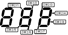
Diagram of switch position indicator
|
TOGGLE SWITCHES | ||||||
|
Function |
Label |
Function |
Label | |||
|
Start or stop test in progress |
BT1 |
Start or stop test in progress |
SW2/3 | |||
|
USER CONFIGURABLE SETTINGS | ||
|
Setting |
Label |
Position |
|
Local digital loopback test enabled |
SW2/4 |
On |
|
Local digital loopback test disabled |
SW2/4 |
Off |
|
Local analog loopback test enabled |
SW2/5 |
On |
|
Local analog loopback test disabled |
SW2/5 |
Off |
|
Local analog loopback with self-test enabled |
SW2/6 |
On |
|
Local analog loopback with self-test disabled |
SW2/6 |
Off |
|
Display switch positions on front panel LCD |
SW2/7 |
On |
|
Do not display switch positions on front panel LCD |
SW2/7 |
Off |
|
Clear all switch positions |
SW2/8 |
On |
|
Normal operation |
SW2/8 |
Off |
Note: For information on SW2/7 please see the diagram above. Lit segments indicate that a switch is on, and unlit ones indicate a switch that is off. Switch settings may also be displayed with the %S command. The usage of SW2/8 is to clear all test modes. All switches should be in the off position before turning SW2/8 on. | ||
|
COMMAND SET SELECTION | ||
|
Setting |
SW2/1 |
SW2/2 |
|
Asynchronous AT |
Off |
Off |
|
Asynchronous V.25bis |
On |
Off |
|
Synchronous V.25bis |
Off |
On |
|
Synchronous, command set disabled |
On |
On |
|
DIAGNOSTIC LED(S) | |||
|
LED |
Color |
Status |
Condition |
|
TST |
Unidentified |
On |
System error has occurred |
|
TST |
Unidentified |
Off |
Modem is functioning normally |
|
TST |
Unidentified |
Blinking |
Modem has detected a data error or is retraining |
|
DCD |
Unidentified |
On |
Carrier signal detected |
|
DCD |
Unidentified |
Off |
Carrier signal not detected |
|
DTR |
Unidentified |
On |
DTR signal is high |
|
DTR |
Unidentified |
Off |
DTR signal is low |
|
RXD |
Unidentified |
Blinking |
Modem is receiving data |
|
RXD |
Unidentified |
Off |
Modem is not receiving data |
|
TXD |
Unidentified |
Blinking |
Modem is transmitting data |
|
TXD |
Unidentified |
Off |
Modem is not transmitting data |
|
SUPPORTED STANDARD COMMANDS |
|
Basic AT Commands |
|
+++, ‘comma’, A/ |
|
A, B, E, H, I, L, M, O, P, Q, T, V, W, X, Y, Z |
|
&D, &F, &G, &M, &P, &T, &W, &X, &Y, &Z |
|
Extended AT Commands |
|
\A, \B, \C, \E, \J, \N, \Q, \T |
|
%A, %C, %E, %F, %G |
|
V.25 Bis Commands |
|
CIC, CRN, CRS, DIC, INC, INV, LSN, PRN, RLN, VAL |
|
Special AT Commands |
|
-J, -K, *H, )M, @M, :E |
|
S-Registers |
|
S0, S1, S2, S3, S4, S5, S6, S7, S8, S9, S10, S12, S14, S16, S18, S22, S23, S25, S26, S27 |
Note: See MHI documentation for complete information. |
Proprietary AT Command Set
|
AUTO-LOGON | |
|
Type: |
Immediate |
|
Format: |
AT [cmds] $An [cmds] |
|
Default: |
0 |
|
Range: |
0 - 9 |
|
Description: |
Performs the auto-logon sequence stored at memory location n. |
|
BIT-MAPPED REGISTER S21 | ||
|
Format |
AT [cmds] S21=n [cmds] | |
|
Default: |
Unidentified | |
|
Range: |
0-253 | |
|
Unit: |
Bit-mapped | |
|
Description: |
Selects jack type, CTS, RTS, DCD, and DSR signals, low DTR action, and the long space disconnect function. | |
|
Bit |
Value |
Function |
|
0 |
0 |
Not used. |
|
2, 1 |
00 01 10 |
CTS follows RTS in data mode; RTS is ignored in command mode. CTS forced high, RTS is ignored. ITU-T V.13 used to simulate half-duplex modes on full-duplex connections. |
|
4, 3 |
00 01 10 11 |
DTR signal ignored. Modem goes to command mode on low DTR. Modem disconnects on low DTR; Auto-Answer is disabled. Modem is initialized on low DTR. |
|
5 |
0 1 |
DCD forced high. DCD normal. |
|
6 |
0 |
Not used. |
|
7 |
0 1 |
Long space disconnect function disabled. Long space disconnect function enabled. |
|
BIT-MAPPED REGISTER :T15 | |||
|
Format: |
AT [cmds] :T15=n [cmds] | ||
|
Default: |
133 | ||
|
Range: |
0 - 229 | ||
|
Description: |
Controls CTS, RTS, and CD signals, synchronous clocks, and V.32 answer tones. | ||
|
Bit |
Value |
Function | |
|
0 |
0 í 1 |
CTS normal during synchronous and direct asynchronous mode retrains. CTS forced low during synchronous and direct asynchronous mode retrains. | |
|
1 |
í 0 |
Not used. | |
|
2 |
0 í 1 |
When &R is set to 0 or 2, RTS is ignored when not connected. When &R is set to 0 or 2, CTS follows RTS when not connected. | |
|
3 |
í 0 |
Not used. | |
|
4 |
í 0 |
Not used. | |
|
5 |
í 01 |
Synchronous clock disabled when not connected. Synchronous clock enabled when not connected. | |
|
6 |
í 01 |
CD follows link negotiation status. When &C is set to 1, CD follows carrier. | |
|
7 |
0 í 1 |
V.32 answer tone phase is normal. V.32 answer tone phase may be reversed. | |
|
BIT-MAPPED REGISTER :T26 | |||
|
Format: |
AT [cmds] :T26=n [cmds] | ||
|
Default: |
0 | ||
|
Range: |
0 - 3 | ||
|
Description: |
Controls billing delay and V.32 answer tone length. | ||
|
Bit |
Value |
Function | |
|
0 |
í 01 |
2-second billing delay enabled. 2-second billing delay disabled. | |
|
1 |
í 01 |
Normal V.32 answer tone length. Short V.32 answer tone length. | |
|
BREAK TYPE | |||||
|
Type: |
Configuration | ||||
|
Format: |
AT [cmds] \Kn [cmds] | ||||
|
Description: |
Configures the response the modem performs in response to a received break signal. | ||||
|
Command |
Break from DTE Reliable/Normal mode |
Break from DTE Direct mode |
Modem receives \B |
Break from remote modem | |
|
\K0 |
Enter command mode, do not send break to remote modem. |
Send break to remote modem immediately, then enter command mode. |
Buffers cleared and break sent to remote modem. |
Buffers cleared and break sent to DTE. | |
|
\K1 |
Buffers cleared and break sent to remote modem. |
Send break to remote modem immediately. |
Buffers cleared and break sent to remote modem. |
Buffers cleared and break sent to DTE. | |
|
\K2 |
Enter command mode, do not send break to remote modem. |
Send break to remote modem immediately, then enter command mode. |
Send break to remote modem immediately. |
Send break to DTE immediately. | |
|
\K3 |
Send break to remote modem immediately. |
Send break to remote modem immediately. |
Send break to remote modem immediately. |
Send break to DTE immediately. | |
|
\K4 |
Enter command mode, do not send break to remote modem. |
Send break to remote modem immediately, then enter command mode. |
Send break to remote modem with transmitted data. |
Break sent with received data to the DTE. | |
|
\K5 |
Send break with transmitted data. |
Send break to remote modem immediately. |
Send break to remote modem with transmitted data. |
Break sent with received data to the DTE. | |
|
CALL RESTORAL TIMER | |
|
Type: |
Configuration |
|
Format: |
AT [cmds] )Hn [cmds] |
|
Default: |
0 |
|
Range: |
0 - 255 |
|
Unit: |
1 minute |
|
Description: |
Sets the amount of time that the modem will attempt to reconnect to a MNP reliable mode call that has terminated abnormally. Setting )H to 0 disables this feature. If the modem reconnects successfully, the call will proceed as if it did not disconnect. |
|
CALL SECURITY | ||
|
Type: |
Configuration | |
|
Format: |
AT [cmds] $Gn [cmds] | |
|
Description: |
Selects whether the modem will use call security procedures on incoming connections. | |
|
Command |
Function | |
|
í $G0 |
Call security disabled. | |
|
$G1 |
Call security enabled. | |
|
CALL SECURITY - DISPLAY PASSWORD TABLE | |
|
Type: |
Immediate |
|
Format: |
AT [cmds] $I [cmds] |
|
Description: |
Displays the list of user IDs, passwords, and permission levels. |
|
CALL SECURITY - LOGON SEQUENCE | |||
|
Type: |
Configuration | ||
|
Format: |
AT [cmds] $Ln [cmds] | ||
|
Description: |
Changes the logon sequence n. Only sequences 5 through 9 are user configurable. The user will be prompted to enter the new logon sequence using the commands listed below. Errors will be indicated after the sequence by caret characters underneath the problem section. | ||
|
Command |
Function | ||
|
An |
Aborts the call if the last string specified to wait for is not received in n seconds. | ||
|
B |
Modem compares the user’s password to the password table. If it does not match the user is given two more tries, then disconnects. If the passwords match the modem acts according to the stored permission level. | ||
|
C |
Modem waits for 15 seconds for the remote modem to disconnect. If it does not then the local modem disconnects, waits five seconds, then calls the user at the number entered. If no number was entered the modem calls the number stored at the location matching the user number. | ||
|
Dn |
Delays for n seconds. | ||
|
Nn |
Waits for the user to enter his user ID. The following options are available: | ||
|
Option |
Function | ||
|
í 0 |
Entered characters are not echoed. | ||
|
1 |
Entered characters are echoed. | ||
|
2 |
Entered characters are echoed as periods. | ||
|
Pn |
Waits for the user to enter his password. The following options are available: | ||
|
Option |
Function | ||
|
í 0 |
Entered characters are not echoed. | ||
|
1 |
Entered characters are echoed. | ||
|
2 |
Entered characters are echoed as periods. | ||
|
CALL SECURITY - LOGON SEQUENCE (CON’T) | ||
|
Command |
Function | |
|
Rn |
Restarts the logon sequence if the last string specified to wait for is not received in n seconds. | |
|
Sn |
Skips to the next section of the logon sequence if the last string specified to wait for is not received in n seconds. | |
|
Vn |
Waits for the user to enter his phone number for a callback sequence. The following options are available: | |
|
Option |
Function | |
|
í 0 |
Entered characters are not echoed. | |
|
1 |
Entered characters are echoed. | |
|
2 |
Entered characters are echoed as periods. | |
|
Z |
Modem compares the user’s password to the password table. If it does not match the user is given two more tries, then disconnects. If the passwords match the sequence continues. | |
|
&n |
Calls the user back with logon sequence n. | |
|
+n |
Continue with logon sequence n. | |
|
‘xxxxx’ |
Sends the string xxxxx to the calling modem. Control characters (including carriage returns) may be entered by preceding the character with a caret.) | |
|
"xxxxx" |
Waits to receive the string xxxxx from the calling modem. | |
|
CALL SECURITY - PASSWORD SELECTION | ||
|
Type: |
Configuration | |
|
Format: |
AT [cmds] $Hn (prompt) AS #n: xxxxxxxx, yyyyyyyy, a | |
|
Description: |
Sets the user ID, password, and permission level for user number n. The xxxxxxxx field indicates the user ID, the yyyyyyyy the password, and the a is the permission level. n must be between 1 and 40. | |
|
Permission |
Function | |
|
a =1 |
User will be connected if correct user ID and password are entered. | |
|
a =2 |
User will be called back at stored phone number n. | |
|
a =3 |
User will be prompted to enter a phone number at which to be called back. If number is not entered, user will be called back at stored phone number n. | |
|
CD, CTS, AND DSR SIGNAL CONNECT TIMER | |
|
Type: |
Register |
|
Format: |
AT [cmds] :T14=n [cmds] |
|
Default: |
0 |
|
Range: |
0 - 255 |
|
Unit: |
.1 second |
|
Description: |
Sets the amount time before or after the connect message that CD, CTS, and DSR will be brought high. |
|
CD, CTS, AND DSR SIGNAL TIMING | ||
|
Type: |
Configuration | |
|
Format: |
AT [cmds] @Cn [cmds] | |
|
Description: |
Selects whether the CD, CTS, and DSR signals are brought high before or after the connect message. | |
|
Command |
Function | |
|
í @C0 |
CD, CTS, and DSR brought high after connect message. | |
|
@C1 |
CD, CTS, and DSR brought high before connect message. | |
|
CD SIGNAL | |
|
Type: |
Configuration |
|
Format: |
AT [cmds] &Cn [cmds] |
|
Description: |
Controls the behaviour of the CD signal. |
|
Command |
Function |
|
&C0 |
CD forced high. |
|
í &C1 |
CD normal. |
|
&C2 |
CD forced high except at disconnect. |
|
CD SIGNAL DELAY | |
|
Type: |
Configuration |
|
Format: |
AT [cmds] :Un [cmds] |
|
Default: |
0 |
|
Range: |
0 - 255 |
|
Unit: |
12.5 mS |
|
Description: |
Selects the amount of time that the modem delays before it brings the CD signal high. |
|
Note: |
This command only takes effect if :R is set to 1. |
|
COMMAND SET | ||
|
Type: |
Configuration | |
|
Format: |
AT [cmds] -Hn [cmds] | |
|
Description: |
Selects whether the modem will accept commands. | |
|
Command |
Function | |
|
í -H0 |
Command sets enabled. | |
|
-H1 |
Command sets disabled. | |
|
CONNECT SPEED MATCHING | ||
|
Type: |
Configuration | |
|
Format: |
AT [cmds] %Ln [cmds] | |
|
Description: |
Selects whether the modem will attempt to match the connect speed of the remote modem. | |
|
Command |
Function | |
|
%L0 |
Modem will connect at speeds supported by the protocol selected only. | |
|
í %L1 |
Modem will match connect speeds. | |
|
%L2 |
Modem will connect only at current speed. | |
|
%L3 |
Modem will use ITU-T automode to match speeds. | |
|
CONNECTION SECURITY - DISPLAY PASSWORD TABLE | |
|
Type: |
Immediate |
|
Format: |
AT [cmds] $N [cmds] |
|
Description: |
Displays the list of connection passwords. |
|
CONNECTION SECURITY - PASSWORD SELECTION (ASYNCHRONOUS MODE) | |
|
Type: |
Configuration |
|
Format: |
AT [cmds] %In [cmds] |
|
Description: |
Changes connection password number n. n must be between 0 and 4. The user will be prompted to enter the old and new passwords. Passwords must be exactly five characters, case insensitive. |
|
CONNECTION SECURITY - PASSWORD SELECTION (SYNCHRONOUS MODE) | |
|
Type: |
Configuration |
|
Format: |
AT [cmds] %In;xxxxx;yyyyy [cmds] |
|
Description: |
Changes connection password number n. n must be between 0 and 4. The xxxxx represents the main security password, and the yyyyy is the new connection password. Passwords must be exactly five characters, case insensitive. |
|
CONNECTION SECURITY - PASSWORD SEND | ||
|
Type: |
Configuration | |
|
Format: |
AT [cmds] $Mn [cmds] | |
|
Description: |
Selects how the modem will attempt to connect to a secure system. | |
|
Command |
Function | |
|
í $M0 |
Modem does not send connection password. | |
|
$M1 |
Modem sends connection password 0. If password does not match any of the remote modem’s connection passwords, the modem disconnects. | |
|
$M2 |
Modem sends connection password 0. If password does not match any of the remote modem’s connection passwords, the remote modem uses logon sequence 5 to give the user three tries to enter a connection password. If this fails, the modem disconnects. | |
|
CTS DELAY TIMER | |
|
Type: |
Register |
|
Format: |
AT [cmds] :T16=n [cmds] |
|
Default: |
0 |
|
Range: |
0 - 255 |
|
Unit: |
12.5 mS |
|
Description: |
Sets the amount of time that the modem waits after a connection has been made and CD and DSR have gone high that the modem brings CTS high. |
|
CTS SIGNAL DELAY | |
|
Type: |
Configuration |
|
Format: |
AT [cmds] :Vn [cmds] |
|
Default: |
0 |
|
Range: |
0 - 255 |
|
Unit: |
12.5 mS |
|
Description: |
Selects the amount of time that the modem delays before it brings the CTS signal high. |
|
DIAL | |
|
Type: |
Immediate |
|
Format: |
AT [cmds] D <#> [cmds] |
|
Description: |
Dials the telephone number indicated according to any modifiers included in the string. |
|
Command |
Function |
|
DA |
MNP10 link will be negotiated at 4800bps for this call. |
|
DJ |
MNP10 link will be negotiated at 1200bps for this call. |
|
DK |
MNP10 power level adjustment enabled for this call. |
|
DL |
Re-dial last number. |
|
DM |
Make a LAPM reliable mode connection this call. |
|
DNn |
If the dial attempt fails, the modem will attempt to dial stored number n. |
|
DO |
This call will be set for a cellular phone. Same as executing the following command: AT \N2 )M1 :E0 @M18 *H1 |
|
DP |
Pulse dialing enabled. |
|
DQ |
Make an LAPM auto-reliable mode connection this call. |
|
DR |
Answer mode enabled; originate mode disabled following handshake initiation. |
|
DS |
Dial the first stored telephone number. |
|
DT |
Tone dialing enabled. |
|
DU |
Make a direct mode connection this call. |
|
DV |
Make an LAPM or MNP reliable mode connection this call. |
|
DW |
Dialing resumed following dial tone detection. |
|
DX |
Make an auto-reliable mode connection this call. |
|
DY |
Make an MNP reliable mode connection this call. |
|
DZ |
Make a normal mode connection this call. |
|
D, |
Dialing paused for amount of time specified in S8 register. |
|
D/n |
Dial stored telephone number n. |
|
D! |
Flash function initiated. Modem commanded to go off-hook for specified time before returning on-hook. |
|
D+n |
Perform logon sequence n after connecting. |
|
D@ |
Wait for Quiet Answer function enabled. Modem waits until a "quiet answer," a ring-back signal followed by silence up to the time specified in S7, is received prior to executing the rest of the dial string. |
|
D$ |
Wait for prompt tone detection function enabled. Waits for prompt tone for amount of time specified by the S7 command. |
|
D; |
Modem returned to idle state after dialing. The semicolon can only be placed at the end of the dial command. |
|
DIAL REPEATEDLY | |
|
Type: |
Immediate |
|
Format: |
AT [cmds] -D <#> [cmds] |
|
Description: |
Dials the number indicated up to nine times. |
|
DISCONNECT BUFFER DELAY | |
|
Type: |
Configuration |
|
Format |
AT [cmds] %Dn [cmds] |
|
Default: |
0 |
|
Range: |
0-255 |
|
Unit: |
1 second |
|
Description: |
Sets maximum duration allowed during buffered data calls for modem to perform clearing functions after losing carrier-signal or receiving a clear call signal from the remote modem and before initiating hang-up process. |
|
DISPLAY CONFIGURATION AND STATISTICS | |
|
Type: |
Immediate |
|
Format: |
AT [cmds] \S [cmds] |
|
Description: |
Displays the settings of all commands and statistics about the current connection. |
|
DISPLAY FIRMWARE VERSION | |
|
Type: |
Immediate |
|
Format: |
AT [cmds] %V [cmds] |
|
Description: |
Displays the current firmware version. |
|
DISPLAY REGISTERS | ||
|
Type: |
Immediate | |
|
Format: |
AT [cmds] %Rn [cmds] | |
|
Description: |
Displays all status registers. | |
|
Command |
Function | |
|
%R0 |
Displays all S registers. | |
|
%R1 |
Displays all :T registers. | |
|
DISPLAY ROM BOOTSTRAP VERSION | |
|
Type: |
Immediate |
|
Format: |
AT [cmds] %V [cmds] |
|
Description: |
Displays the current ROM bootstrap version. |
|
DISPLAY STORED NUMBERS | |
|
Type: |
Immediate |
|
Format: |
AT [cmds] \F [cmds] |
|
Description: |
Displays all stored telephone numbers. |
|
DISPLAY STORED SWITCH CONFIGURATION | |
|
Type: |
Immediate |
|
Format: |
AT [cmds] -X [cmds] |
|
Description: |
Displays the stored switch configuration. See the switch settings for more information. |
|
DISPLAY SWITCH SETTINGS | ||
|
Type: |
Immediate | |
|
Format: |
AT [cmds] %Sn [cmds] | |
|
Description: |
Displays the settings of SW1 and SW2. | |
|
Command |
Function | |
|
%S0 |
Display settings of SW1/1-SW1/4. | |
|
%S1 |
Display settings of SW2/1-SW2/8. | |
|
DSR DISCONNECT TIMER | |
|
Type: |
Register |
|
Format: |
AT [cmds] :T22=n [cmds] |
|
Default: |
34 |
|
Range: |
0 - 255 |
|
Unit: |
12.5 mS |
|
Description: |
Sets the amount of time that the modem waits after disconnecting to lower DSR. |
|
DSR AND CTS SIGNALS | |
|
Type: |
Configuration |
|
Format: |
AT [cmds] \Dn [cmds] |
|
Description: |
Controls the behaviour of the DSR and CTS signals. |
|
Command |
Function |
|
í \D0 |
DSR and CTS forced high. |
|
\D1 |
CTS follows CD. If &C is not set to 1 then DSR also follows CD, otherwise it follows OH. |
|
\D2 |
DSR and CTS follow CD. |
|
\D3 |
DSR normal, CTS forced high. |
|
\D4 |
DSR and CTS normal. |
|
DSR SIGNAL DELAY | |
|
Type: |
Configuration |
|
Format: |
AT [cmds] :Vn [cmds] |
|
Default: |
0 |
|
Range: |
0 - 255 |
|
Unit: |
12.5 mS |
|
Description: |
Selects the amount of time that the modem delays before it brings the DSR signal high. |
|
ENQ/ACK PROTOCOL | ||
|
Type: |
Configuration | |
|
Format: |
AT [cmds] \Hn [cmds] | |
|
Description: |
Selects the Hewlett-Packard ENQ/ACK protocol. | |
|
Command |
Function | |
|
í \H0 |
ENQ/ACK protocol disabled. | |
|
\H1 |
ENQ/ACK protocol enabled in terminal mode. | |
|
\H2 |
ENQ/ACK protocol enabled in host mode. | |
|
ESCAPE AND FLOW CONTROL CHARACTER PARITY CHECKING | ||
|
Type: |
Configuration | |
|
Format: |
AT [cmds] -Pn [cmds] | |
|
Description: |
Selects whether the modem checks the parity of incoming escape and flow control characters. | |
|
Command |
Function | |
|
-P0 |
Parity checking of flow control and escape characters disabled. | |
|
-P1 |
Flow control and escape characters will be processed only if their parity matches serial port. | |
|
-P2 |
Escape characters will be processed only if their parity matches serial port. | |
|
EXTENDED RESULT CODES | ||
|
Type: |
Configuration | |
|
Format: |
AT [cmds] \Vn [cmds] | |
|
Description: |
Selects what form of result codes will be issued. | |
|
Command |
Function | |
|
\V0 |
Extended result codes disabled. | |
|
\V1 |
/REL added to reliable mode connections; CONNECT/9600 given for all speeds between 4800bps and 12Kbps. | |
|
í \V2 |
Error correction protocol result codes enabled; CONNECT/9600 given for all speeds between 4800bps and 12Kbps | |
|
\V3 |
/REL added to reliable mode connections when verbose result codes are used; standard numeric result codes are used. | |
|
\V4 |
Error correction protocol result codes enabled. | |
|
FIRMWARE UPLOAD | |
|
Type: |
Immediate |
|
Format: |
AT [cmds] ^C1 [cmds] |
|
Description: |
Initiates a transfer of a new firmware file. |
|
FIRMWARE UPLOAD | |
|
Type: |
Immediate |
|
Format: |
AT [cmds] ^H [cmds] |
|
Description: |
Initiates an ASCII transfer of a new firmware file. |
|
FLOW CONTROL - MODEM TO MODEM | |
|
Type: |
Configuration |
|
Format: |
AT [cmds] \Gn [cmds] |
|
Description: |
Selects the type of modem-to-modem flow control used. |
|
Command |
Function |
|
í \G0 |
Flow control disabled. |
|
\G1 |
Bidirectional flow control enabled. |
|
\G2 |
Unidirectional flow control enabled. |
|
FLOW CONTROL CHARACTER - XOFF PRIMARY | |
|
Type: |
Register |
|
Format: |
AT [cmds] :T10=n [cmds] |
|
Default: |
19 |
|
Range: |
0-255 |
|
Unit: |
ASCII |
|
Description: |
Sets the primary XOFF character. |
|
FLOW CONTROL CHARACTER - XOFF SECONDARY | |
|
Type: |
Register |
|
Format: |
AT [cmds] :T12=n [cmds] |
|
Default: |
251 |
|
Range: |
0-255 |
|
Unit: |
ASCII |
|
Description: |
Sets the secondary XOFF character. |
|
FLOW CONTROL CHARACTER - XON PRIMARY | |
|
Type: |
Register |
|
Format: |
AT [cmds] :T9=n [cmds] |
|
Default: |
17 |
|
Range: |
0-255 |
|
Unit: |
ASCII |
|
Description: |
Sets the primary XON character. |
|
FLOW CONTROL CHARACTER - XON SECONDARY | |
|
Type: |
Register |
|
Format: |
AT [cmds] :T11=n [cmds] |
|
Default: |
249 |
|
Range: |
0-255 |
|
Unit: |
ASCII |
|
Description: |
Sets the secondary XON character. |
|
ITU-T AUTOMODE TIMER | |
|
Type: |
Register |
|
Format: |
AT [cmds] :T13=n [cmds] |
|
Default: |
15 |
|
Range: |
0 - 255 |
|
Unit: |
.1 second |
|
Description: |
Sets the amount of time the modem attempts to connect with ITU-T automode before disconnecting. |
|
KERMIT AND UUCP PROTOCOLS | ||
|
Type: |
Configuration | |
|
Format: |
AT [cmds] :Kn [cmds] | |
|
Description: |
Controls the Kermit and UUCP transfer protocols. | |
|
Command |
Function | |
|
í :K0 |
Kermit and UUCP protocols disabled. | |
|
:K1 |
Kermit protocol enabled. | |
|
:K2 |
UUCP G protocol enabled. | |
|
KERMIT MARK CHARACTER | |
|
Type: |
Configuration |
|
Format: |
AT [cmds] :Qn [cmds] |
|
Default: |
1 |
|
Range: |
0 - 31 |
|
Unit: |
1 ASCII character |
|
Description: |
Sets the character that will be used as the beginning of packet marker when in Kermit protocol mode. |
|
LINE SPEED | ||
|
Type: |
Configuration | |
|
Format: |
AT [cmds] %Bn [cmds] | |
|
Description: |
Sets the speed that the modem will communicate with the DTE. | |
|
Command |
Function | |
|
%B75 |
Sets the serial port to 75bps. | |
|
%B300 |
Sets the serial port to 300bps. | |
|
%B600 |
Sets the serial port to 600bps. | |
|
%B1200 |
Sets the serial port to 1200bps. | |
|
%B2400 |
Sets the serial port to 2400bps. | |
|
%B4800 |
Sets the serial port to 4800bps. | |
|
%B7200 |
Sets the serial port to 7200bps. | |
|
%B9600 |
Sets the serial port to 9600bps. | |
|
%B12000 |
Sets the serial port to 12Kbps. | |
|
%B14400 |
Sets the serial port to 14.4Kbps. | |
|
%B19200 |
Sets the serial port to 19.2Kbps. | |
|
%B16800 |
Sets the serial port to 38.4Kbps. | |
|
%B19200 |
Sets the serial port to 57.6Kbps. | |
|
%B21600 |
Sets the serial port to 21.6Kbps. | |
|
%B24000 |
Sets the serial port to 24Kbps. | |
|
%B26400 |
Sets the serial port to 26.4Kbps. | |
|
%B28800 |
Sets the serial port to 28.8Kbps. | |
|
LINE TYPE | ||
|
Type: |
Configuration | |
|
Format: |
AT [cmds] &Ln [cmds] | |
|
Description: |
Selects what type of line the modem is connected to and whether it will attempt to automatically re-connect. | |
|
Command |
Function | |
|
í &L0 |
Modem is connected to switched line. | |
|
&L1 |
Modem is connected to 2-wire leased line. | |
|
&L2 |
Modem is connected to 2-wire leased line. After 6 seconds of receiving no input, the modem goes off-hook and attempts to connect. | |
|
LOCAL SERIAL PORT SPEED | ||
|
Type: |
Configuration | |
|
Format: |
AT [cmds] $Bn [cmds] | |
|
Description: |
Sets the speed that the modem will communicate with the DTE. | |
|
Command |
Function | |
|
$B75 |
Sets the serial port to 75bps. | |
|
$B300 |
Sets the serial port to 300bps. | |
|
$B600 |
Sets the serial port to 600bps. | |
|
$B1200 |
Sets the serial port to 1200bps. | |
|
$B2400 |
Sets the serial port to 2400bps. | |
|
$B4800 |
Sets the serial port to 4800bps. | |
|
$B9600 |
Sets the serial port to 9600bps. | |
|
$B19200 |
Sets the serial port to 19.2Kbps. | |
|
$B38400 |
Sets the serial port to 38.4Kbps. | |
|
$B57600 |
Sets the serial port to 57.6Kbps. | |
|
$B115200 |
Sets the serial port to 115.2Kbps. | |
|
LOCAL SERIAL PORT SPEED MATCHING | ||
|
Type: |
Configuration | |
|
Format: |
AT [cmds] %Gn [cmds] | |
|
Description: |
Selects whether the speed of the modem’s port will be changed to match the local serial port, or if the user must do it by hand. | |
|
Command |
Function | |
|
í %G0 |
Speed changed automatically. | |
|
%G1 |
User must change speed with %B command. | |
|
LOCAL SERIAL PORT SPEED RESET | ||
|
Type: |
Configuration/Immediate | |
|
Format: |
AT [cmds] %Un [cmds] | |
|
Description: |
Selects when the speed of the serial port may change. | |
|
Note: |
When the serial port speed is changed from 38.4Kbps, a %U command must be entered for the modem to recognize the new speed. | |
|
Command |
Function | |
|
í %U0 |
Serial port speed may change at any time. Modem will automatically adjust. | |
|
%U1 |
Modem will only adapt to serial port speed change when %U1 is entered. | |
|
%U2 |
Serial port speed may change at any time. Modem will automatically adjust. | |
|
LOGON SEQUENCE DISPLAY | ||
|
Type: |
Configuration | |
|
Format: |
AT [cmds] $Vn [cmds] | |
|
Description: |
Controls whether the modem displays the text of the logon sequence. | |
|
Command |
Function | |
|
$V0 |
Logon sequence not displayed. | |
|
í $V1 |
Logon sequence displayed. | |
|
LOOPBACK TEST AND BUSY OUT CONFIGURATION | ||
|
Type: |
Configuration | |
|
Format: |
AT [cmds] %Hn [cmds] | |
|
Description: |
Controls the functions of serial port pins 18 and 21. | |
|
Command |
Function | |
|
í %H0 |
Pins 18 and 21 have no function. | |
|
%H1 |
Busy Out when pin 18 is high, perform local analog loopback test on high DTR. | |
|
%H2 |
Perform local analog loopback test when pin 18 is high, remote digital loopback test when pin 21 is high. | |
|
LOW DTR BUSY OUT TIMER | |
|
Type: |
Register |
|
Format: |
AT [cmds] :T18=n [cmds] |
|
Default: |
0 |
|
Range: |
0 - 255 |
|
Unit: |
1 second |
|
Description: |
Sets the amount of time that the modem waits after DTR has gone low to busy out the line. The modem does not busy out the line when :T18 is set to 0. |
|
MANUAL DIAL CONFIGURATION | ||
|
Type: |
Configuration | |
|
Format: |
AT [cmds] :Dn [cmds] | |
|
Description: |
Selects when the modem goes off-hook to accept a manually dialed call. | |
|
Command |
Function | |
|
í :D0 |
Modem does not respond when DTR goes high. | |
|
:D1 |
Modem goes off hook in originate mode when DTR goes high. | |
|
:D2 |
Modem dials first stored number when DTR goes high or when Talk/Data button is pressed | |
|
MNP10 1200BPS DISCONNECT | ||
|
Type: |
Register | |
|
Format: |
AT [cmds] :T19=n [cmds] | |
|
Description: |
Selects whether the modem will disconnect an idle 1200bps MNP10 connection. | |
|
Command |
Function | |
|
:T19=0 |
Modem will not disconnect an idle connection. | |
|
í :T19=1 |
Modem will disconnect an idle connection after 2 minutes. | |
|
MNP10 FALLBACK | |
|
Type: |
Configuration |
|
Format: |
AT [cmds] -Qn [cmds] |
|
Description: |
Allows MNP10 to fall back to speeds slower than 4800bps |
|
Command |
Function |
|
-Q0 |
MNP10 at 2400bps and 1200bps disabled. |
|
-Q1 |
MNP10 at 2400bps enabled. |
|
í -Q2 |
MNP10 at 2400bps and 1200bps enabled. |
|
ORIGINATE/ANSWER MODE | ||
|
Type: |
Configuration | |
|
Format: |
AT [cmds] $On [cmds] | |
|
Description: |
Selects whether the modem will function in originate or answer mode. | |
|
Command |
Function | |
|
í $O0 |
Originate/Answer button determines mode. | |
|
$O1 |
Modem operates in originate mode. | |
|
$O2 |
Modem operates in answer mode. | |
|
PARALLEL PORT PACKET SIZE | |
|
Type: |
Register |
|
Format: |
AT [cmds] :T29=n [cmds] |
|
Default: |
32 |
|
Range: |
0 - 63 |
|
Unit: |
1 byte |
|
Description: |
Sets the size of packets sent over the parallel port. |
|
PARITY | ||
|
Type: |
Configuration | |
|
Format: |
AT [cmds] -On [cmds] | |
|
Description: |
Selects the serial parity that the modem will use. | |
|
Command |
Function | |
|
-O0 |
Modem will use seven data bits, odd parity. | |
|
-O1 |
Modem will use seven data bits, even parity. | |
|
-O2 |
Modem will use seven data bits, MARK parity. | |
|
-O3 |
Modem will use seven data bits, SPACE parity. | |
|
í -O4 |
Modem will use eight data bits, no parity. | |
|
-O5 |
Modem will use eight data bits, odd parity. | |
|
-O6 |
Modem will use eight data bits, even parity. | |
|
-O7 |
Modem will use eight data bits, MARK parity. | |
|
POWER-UP DIAGNOSTICS | |
|
Type: |
Immediate |
|
Format: |
AT [cmds] $D [cmds] |
|
Description: |
Performs power-up diagnostic routines. If SW1 and SW2 are all on, performs a reset and diagnostic routines. |
|
PULSES PER DIGIT | |
|
Type: |
Configuration |
|
Format: |
AT [cmds] %Wn [cmds] |
|
Description: |
Sets the number of pulses per digit dialed while in pulse mode. |
|
Command |
Function |
|
í %W0 |
Digit value is number of pulses generated (0 digit generates 10 pulses). |
|
%W1 |
Digit value plus one pulses generated (0 digit generates 1 pulse). |
|
%W2 |
Ten minus digit value pulses generated (0 digit generates 10 pulses). |
|
REMOTE CONFIGURATION | ||
|
Type: |
Configuration | |
|
Format: |
AT [cmds] *En [cmds] | |
|
Description: |
Selects whether a modem will accept requests for remote configuration. | |
|
Command |
Function | |
|
í *E0 |
Remote configuration disabled. | |
|
*E1 |
Remote configuration enabled. | |
|
REMOTE CONFIGURATION CHARACTER | |
|
Type: |
Configuration |
|
Format: |
AT [cmds] *Sn [cmds] |
|
Default: |
42 |
|
Range: |
0 - 126 |
|
Unit: |
1 ASCII character |
|
Description: |
Defines the character that the *A command will send four times within the guard time set by S12 to notify the remote modem that a remote configuration session is requested. |
|
REMOTE CONFIGURATION BANNER | |
|
Type: |
Configuration |
|
Format: |
AT [cmds] *I [cmds] |
|
Description: |
Sets the banner that the modem displays when a remote configuration session is begun. The user will be prompted to enter the banner, which can be no longer than 25 characters. |
|
REMOTE CONFIGURATION RECOVERY | |
|
Type: |
Immediate |
|
Format: |
AT [cmds] *Q [cmds] |
|
Description: |
Recovers changes made during a remote configuration session that were not saved. |
|
REMOTE CONFIGURATION - REDUCE ACCESS | |
|
Type: |
Immediate |
|
Format: |
AT [cmds] *X [cmds] |
|
Description: |
Removes a level of access during a remote configuration session. If the user has full access, it will be reduced to read-only; if at read-only, the session will be ended. |
|
REMOTE CONFIGURATION REQUEST | |
|
Type: |
Immediate |
|
Format: |
AT [cmds] *A [cmds] |
|
Description: |
Requests to begin a remote configuration session with the remote modem. |
|
Note: |
The same function may be accomplished by sending the remote configuration character four times within the guard time set by register S12. |
|
REMOTE CONFIGURATION SAVE | |
|
Type: |
Immediate |
|
Format: |
AT [cmds] *U [cmds] |
|
Description: |
Saves the changes that have been made to the remote configuration. |
|
REMOTE CONFIGURATION SECURITY | ||
|
Type: |
Configuration | |
|
Format: |
AT [cmds] *Rn [cmds] | |
|
Description: |
Selects whether remote configuration sessions are password protected. | |
|
Command |
Function | |
|
í *R0 |
Remote configuration security disabled. | |
|
*R1 |
Remote configuration security enabled. | |
|
REMOTE CONFIGURATION SECURITY - FULL ACCESS REQUEST | |
|
Type: |
Immediate |
|
Format: |
AT [cmds] *M [cmds] |
|
Description: |
Requests the remote modem to grant the user full configuration access. If remote configuration security is enabled, the user will be given three chances to enter the password. If this fails, full access will not be granted. |
|
REMOTE CONFIGURATION SECURITY - PASSWORD SELECTION | ||
|
Type: |
Configuration | |
|
Format: |
AT [cmds] *Pn | |
|
Description: |
Changes the passwords for remote configuration. The user will be prompted to enter the old and new passwords. Passwords must be exactly five characters, case insensitive. | |
|
Command |
Function | |
|
*P0 |
Sets the read-only remote configuration password. | |
|
*P1 |
Sets the full access remote configuration password. | |
|
RESULT CODES - MNP | ||
|
Type: |
Configuration | |
|
Format: |
AT [cmds] -Mn [cmds] | |
|
Description: |
Selects whether the modem will give MNP result codes. | |
|
Command |
Function | |
|
í -M0 |
MNP result codes disabled. | |
|
-M1 |
MNP result codes enabled. | |
|
RI SIGNAL | ||
|
Type: |
Configuration | |
|
Format: |
AT [cmds] \Rn [cmds] | |
|
Description: |
Selects when the RI signal will be cleared from an incoming call. | |
|
Command |
Function | |
|
\R0 |
RI signal not cleared until the call has disconnected. | |
|
í \R1 |
RI signal cleared when call is answered. | |
|
RING SIMULATION | ||
|
Type: |
Configuration | |
|
Format: |
AT [cmds] :Rn [cmds] | |
|
Description: |
Selects whether the modem simulates the ring signal an incoming call if the DSTR signal is low. | |
|
Command |
Function | |
|
í :R0 |
Modem does not simulate a ring signal. | |
|
:R1 |
Modem simulates ring on low DTR and if &D command is not set to 0. After 30 seconds if DTR does not go high, the modem "disconnects" the simulated call. If &D is set to 0 or the DTR signal is high, the modem attempts to connect immediately. | |
|
SYNCHRONOUS RTS AND CTS SIGNALS | |
|
Type: |
Configuration |
|
Format: |
AT [cmds] &Rn [cmds] |
|
Description: |
Controls the behaviour of the RTS and CTS signals. |
|
Command |
Function |
|
í &R0 |
CTS follows RTS in data mode; RTS is ignored in command mode. |
|
&R1 |
CTS forced high, RTS is ignored. |
|
&R2 |
ITU-T V.13 used to simulate half-duplex modes on full-duplex connections. |
|
SECONDARY FLOW CONTROL | ||
|
Type: |
Configuration | |
|
Format: |
AT [cmds] -Fn [cmds] | |
|
Description: |
Selects whether the secondary flow control characters will be active. | |
|
Command |
Function | |
|
í -F0 |
Secondary flow control disabled. | |
|
-F1 |
Secondary flow control enabled. | |
|
SECURITY - CLEAR PASSWORDS | ||
|
Type: |
Configuration | |
|
Format: |
AT [cmds] $Jn [cmds] | |
|
Description: |
Clears sections of the password lists. | |
|
Command |
Function | |
|
$J0 |
Clears the call password table and resets the logon sequences to their factory defaults. | |
|
$J1 |
Clears all stored numbers, the call and connection password tables, and resets the logon sequences to their factory defaults. | |
|
SECURITY - MAIN PASSWORD (ASYNCHRONOUS MODE) | |
|
Type: |
Configuration |
|
Format: |
AT [cmds] $P [cmds] |
|
Description: |
Changes the main security password. The user will be prompted for the old and new passwords. Passwords must be exactly five characters, case insensitive. |
|
SECURITY - MAIN PASSWORD (SYNCHRONOUS MODE) | |
|
Type: |
Configuration |
|
Format: |
AT [cmds] $Pxxxxx;yyyyy; [cmds] |
|
Description: |
Changes the main security password. The user will be prompted for the old and new passwords. The xxxxx represents the old password, and the yyyyy is the new password. Passwords must be exactly five characters, case insensitive. |
|
STORE COMPLETE ACTIVE PROFILE | ||
|
Type: |
Immediate | |
|
Format: |
AT [cmds] *Wn [cmds] | |
|
Description: |
Writes all the values for the active profile, including S-registers not normally saved, into the non-volatile RAM. | |
|
Command |
Function | |
|
*W0 |
Write the active profile to stored profile 0 | |
|
*W1 |
Write the active profile to stored profile 1 | |
|
*W2 |
Write the active profile to stored profile 2 | |
|
*W3 |
Write the active profile to stored profile 3 | |
|
STORE TELEPHONE NUMBER | |
|
Type: |
Configuration |
|
Format: |
AT [cmds] \Pn <#> |
|
Description: |
Stores the telephone number indicated at memory location n. |
|
SWITCH CONFIGURATIONS | ||
|
Type: |
Configuration | |
|
Format: |
AT [cmds] $Kn [cmds] | |
|
Description: |
Selects whether the modem will use the configurations stored by SW1 and SW2. | |
|
Command |
Function | |
|
í $K0 |
Switch configurations enabled. | |
|
$K1 |
Switch configurations disabled. | |
|
TALK/DATA MODE | ||
|
Type: |
Configuration | |
|
Format: |
AT [cmds] $Tn [cmds] | |
|
Description: |
Controls the function of the Talk/Data button and selects which mode the modem is in. | |
|
Command |
Function | |
|
í $T0 |
Talk/Data button enabled. | |
|
$T1 |
Talk/Data button disabled. | |
|
$T2 |
Toggles talk/data mode. | |
|
V.21 AND V.23 ANSWER TONE TIMER | |
|
Type: |
Register |
|
Format: |
AT [cmds] :T3=n [cmds] |
|
Default: |
33 |
|
Range: |
0 - 33 |
|
Unit: |
.1 second |
|
Description: |
Sets the length of time the modem will send the V.21 and V.23 answer tone or wait after the answer tone is sent before attempting to complete the connection. |
|
V.21 NEGOTIATION TIMER | |
|
Type: |
Register |
|
Format: |
AT [cmds] :T2=n [cmds] |
|
Default: |
0 |
|
Range: |
0 - 255 |
|
Unit: |
.1 second |
|
Description: |
Sets the amount of time the modem will attempt to make a V.21 connection before giving up and attempting a V.23 half-duplex connection. If this register is set to 0 the modem will not attempt to make a V.23 connection and disconnects instead. |
|
V.22, V.22bis, AND V.32 NEGOTIATION TIMER | |
|
Type: |
Register |
|
Format: |
AT [cmds] :T0=n [cmds] |
|
Default: |
40 |
|
Range: |
0 - 255 |
|
Unit: |
.1 second |
|
Description: |
Sets the amount of time the modem will attempt to make a V.22, V.22bis, or V.32 connection before giving up and attempting a V.23 split speed connection. |
|
V.23 EQUALIZERS | ||
|
Type: |
Configuration | |
|
Format: |
AT [cmds] %On [cmds] | |
|
Description: |
Selects whether the modem will use equalizers when operating in V.23 half-duplex mode. | |
|
Command |
Function | |
|
%O0 |
V.23 equalizers disabled. | |
|
í %O1 |
V.23 equalizers enabled. | |
|
V.23 HALF DUPLEX CARRIER TURNAROUND TIMER | |
|
Type: |
Register |
|
Format: |
AT [cmds] :T4=n [cmds] |
|
Default: |
20 |
|
Range: |
0 - 255 |
|
Unit: |
12.5 mS |
|
Description: |
Sets the amount of time that the modem waits for the remote modem to answer after lowering the carrier signal before it raises the carrier again and begins sending data. |
|
V.23 HALF DUPLEX DCD TIMER | |
|
Type: |
Register |
|
Format: |
AT [cmds] :T6=n [cmds] |
|
Default: |
200 |
|
Range: |
0 - 255 |
|
Unit: |
1 mS |
|
Description: |
Sets the amount of time the modem waits after carrier is raised before it watches for incoming data. |
|
V.23 HALF DUPLEX END-OF-BUFFER CARRIER TIMER | |
|
Type: |
Register |
|
Format: |
AT [cmds] :T5=n [cmds] |
|
Default: |
7 |
|
Range: |
0 - 255 |
|
Unit: |
12.5 mS |
|
Description: |
Sets the amount of time that the modem waits after emptying its transmit buffer before it lowers the carrier signal. |
|
V.23 HALF DUPLEX INACTIVE ANSWER TIMER | |
|
Type: |
Register |
|
Format: |
AT [cmds] :T7=n [cmds] |
|
Default: |
60 |
|
Range: |
0 - 255 |
|
Unit: |
1 second |
|
Description: |
Sets the amount time after a connection is made that if no data is received the modem will disconnect. |
|
V.23 SPLIT SPEED NEGOTIATION TIMER | |
|
Type: |
Register |
|
Format: |
AT [cmds] :T1=n [cmds] |
|
Default: |
30 |
|
Range: |
0 - 255 |
|
Unit: |
.1 second |
|
Description: |
Sets the amount of time the modem will attempt to make a V.23 split speed connection before giving up and attempting a V.23 half-duplex or V.21 connection. If this register is set to 0 the modem will not attempt to make a V.23 connection. |
|
V.32 AND V.32bis TRAINING TIMER | |
|
Type: |
Register |
|
Format: |
AT [cmds] :T17=n [cmds] |
|
Default: |
0 |
|
Range: |
0,1,5 - 32 |
|
Unit: |
Unidentified |
|
Description: |
Sets the amount of time that the modem lets a V.32 or V.32bis connection train before picking a speed. A setting of 0 is equivalent to a setting of 28. Longer training times reduce noise sensitivity. |
|
V.32 TRAINING ON CONNECTION | ||
|
Type: |
Register | |
|
Format: |
AT [cmds] :T23=n [cmds] | |
|
Description: |
Selects whether the modem performs a training sequence at the beginning of a V.32 connection. | |
|
Command |
Function | |
|
:T23=0 |
Modem does not perform training sequence. | |
|
:T23=32 |
Modem performs training sequence. | |
|
WORD LENGTH | ||
|
Type: |
Configuration | |
|
Format: |
AT [cmds] -En [cmds] | |
|
Description: |
Sets the number of bits the modems will use per data word. | |
|
Command |
Function | |
|
í -E0 |
Use 10-bit words. | |
|
-E1 |
Use 11-bit words. | |
Proprietary V.25bis Command Set
|
CLEAR STORED NUMBERS | |
|
Type: |
Configuration |
|
Format: |
CLAnn |
|
Description: |
Clears stored number location nn. If no number is given, all memory locations are cleared. |
|
CONNECT | |
|
Type: |
Result code |
|
Format: |
ONLnnnn |
|
Description: |
Reports that the modem has connected at nnnn bps. |
|
CONNECTING | |
|
Type: |
Result code |
|
Format: |
CNX |
|
Description: |
Reports that the modem is attempting to connect. |
|
DISPLAY CONFIGURATION AND STATISTICS | |
|
Type: |
Immediate |
|
Format: |
RS3 |
|
Description: |
Displays the settings of all commands and statistics about the current connection. |
|
HANG UP | |
|
Type: |
Immediate |
|
Format: |
HUP |
|
Description: |
Commands the modem to go on hook. |
|
LOCAL SERIAL PORT SPEED | ||
|
Type: |
Configuration | |
|
Format: |
CSPnn | |
|
Description: |
Sets the speed that the modem will communicate with the DTE. | |
|
Command |
Function | |
|
CSP75 |
Sets the serial port to 75bps. | |
|
CSP300 |
Sets the serial port to 300bps. | |
|
CSP600 |
Sets the serial port to 600bps. | |
|
CSP1200 |
Sets the serial port to 1200bps. | |
|
CSP2400 |
Sets the serial port to 2400bps. | |
|
CSP4800 |
Sets the serial port to 4800bps. | |
|
CSP9600 |
Sets the serial port to 9600bps. | |
|
CSP19200 |
Sets the serial port to 19.2Kbps. | |
|
CSP38400 |
Sets the serial port to 38.4Kbps. | |
|
CSP57600 |
Sets the serial port to 57.6Kbps. | |
|
CSP115200 |
Sets the serial port to 115.2Kbps. | |
|
OFF-LINE | |
|
Type: |
Result code |
|
Format: |
OFL |
|
Description: |
Reports that the connection has been terminated. |
|
ON-LINE | |
|
Type: |
Immediate |
|
Format: |
RDS |
|
Description: |
Instructs the modem to return to on-line state. |
|
REDIAL | |
|
Type: |
Immediate |
|
Format: |
DLN |
|
Description: |
Redials the last number dialed. |
|
RESET | |
|
Type: |
Immediate |
|
Format: |
ITN |
|
Description: |
Resets the modem to power-up defaults. |
|
STORE ACTIVE PROFILE | |
|
Type: |
Immediate |
|
Format: |
PRC |
|
Description: |
Stores the active V.25bis profile in configuration 0. |
|
V.25bis STANDARD SELECTION | ||
|
Type: |
Configuration | |
|
Format: |
AT@Bn | |
|
Description: |
Selects which standard the V.25bis commands will follow. | |
|
Command |
Function | |
|
í AT@B0 |
V.25bis result codes follow ITU-T Red Book. Only V.25bis dial modifiers supported. The only valid result codes are CFI, INC, INV, and VAL. | |
|
AT@B1 |
V.25bis result codes follow ITU-T Blue Book. Only V.25bis dial modifiers supported. The only valid result codes are CFI, CNX, INC, INV, and VAL. | |
|
AT@B2 |
All V.25bis result codes supported. Only V.25bis dial modifiers supported. | |
|
AT@B4 |
V.25bis result codes follow ITU-T Red Book. Only AT dial modifiers supported. The only valid result codes are CFI, INC, INV, and VAL. | |
|
AT@B5 |
V.25bis result codes follow ITU-T Blue Book. Only AT dial modifiers supported. The only valid result codes are CFI, CNX, INC, INV, and VAL. | |
|
AT@B6 |
All V.25bis result codes supported. Only AT dial modifiers supported. | |