CTC UNION TECHNOLOGIES CO., LTD
G.703 FE1 FRACTIONAL E1
G.703 FRACTIONAL T1
|
Card Type |
Fractional Access Unit |
|
NIC Type |
E1/T1 |
|
Chip Set |
Unidentified |
|
I/O Options |
25-pin DTE/DCE port, BNC connectors (2), RJ-45 connector |
|
Wiring Type |
RJ-45 120ohm shielded twisted pair BNC 75ohm coaxial |
|
Maximum Data Rate |
2048Kbps |
|
Data Bus |
External |
|
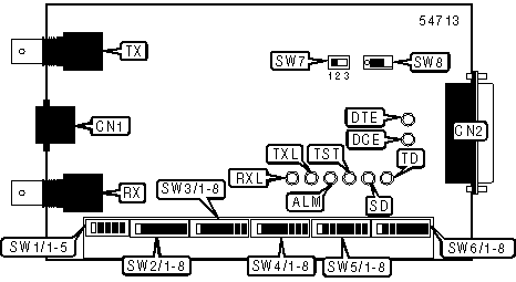
CONNECTIONS | |||
|
Function |
Label |
Function |
Label |
|
RJ-45 connector |
CN1 |
BNC connector - transmit |
TX |
|
25-pin serial connector |
CN2 |
Power switch |
SW8 |
|
BNC connector - receive |
RX | ||
|
USER CONFIGURABLE SETTINGS | |||
|
Setting |
Label |
Position | |
| » |
Unframe mode enabled |
SW2/1 |
Off |
|
Frame mode enabled |
SW2/1 |
On | |
| » |
Normal clock polarity - receive |
SW6/3 |
Off |
|
Inverted clock polarity - receive |
SW6/3 |
On | |
| » |
Normal clock polarity - transmit |
SW6/4 |
Off |
|
Inverted clock polarity - transmit |
SW6/4 |
On | |
| » |
CRC4 disabled |
SW6/5 |
Off |
|
CRC4 enabled |
SW6/5 |
On | |
| » |
CAS/PCM30 mode |
SW6/6 |
Off |
|
CAS/PCM31 mode |
SW6/6 |
On | |
| » |
Unused timeslot - Mark |
SW6/7 |
Off |
|
Unused timeslot - Pass-through |
SW6/7 |
On | |
| » |
DCE data port enabled |
SW6/8 |
Off |
|
DTE data port enabled |
SW6/8 |
On | |
|
Note: When cascading, SW6/7 must be set to on. | |||
|
LINE IMPEDANCE | ||||||
|
Setting |
SW1/1 |
SW1/2 |
SW1/3 |
SW1/4 |
SW1/5 | |
| » |
75ohm unbalanced network interface |
Off |
Off |
On |
On |
On |
|
120ohm balanced network interface |
On |
On |
Off |
Off |
Off | |
|
TIMESLOT SELECTION | |||||||
|
Setting |
SW2/2 |
SW2/3 |
SW2/4 |
SW2/5 |
SW2/6 |
SW2/7 |
SW2/8 |
|
Timeslot 1 active |
On |
Off |
Off |
Off |
Off |
Off |
Off |
|
Timeslot 2 active |
Off |
On |
Off |
Off |
Off |
Off |
Off |
|
Timeslot 3 active |
Off |
Off |
On |
Off |
Off |
Off |
Off |
|
Timeslot 4 active |
Off |
Off |
Off |
On |
Off |
Off |
Off |
|
Timeslot 5 active |
Off |
Off |
Off |
Off |
On |
Off |
Off |
|
Timeslot 6 active |
Off |
Off |
Off |
Off |
Off |
On |
Off |
|
Timeslot 7 active |
Off |
Off |
Off |
Off |
Off |
Off |
On |
|
Note: Off position sets timeslots to idle. Cascaded units must not be assigned identical or overlapping timeslots | |||||||
|
TIMESLOT SELECTION (CONT.) | ||||||||
|
Setting |
SW3/1 |
SW3/2 |
SW3/3 |
SW3/4 |
SW3/5 |
SW3/6 |
SW3/7 |
SW3/8 |
|
Timeslot 8 active |
On |
Off |
Off |
Off |
Off |
Off |
Off |
Off |
|
Timeslot 9 active |
Off |
On |
Off |
Off |
Off |
Off |
Off |
Off |
|
Timeslot 10 active |
Off |
Off |
On |
Off |
Off |
Off |
Off |
Off |
|
Timeslot 11 active |
Off |
Off |
Off |
On |
Off |
Off |
Off |
Off |
|
Timeslot 12 active |
Off |
Off |
Off |
Off |
On |
Off |
Off |
Off |
|
Timeslot 13 active |
Off |
Off |
Off |
Off |
Off |
On |
Off |
Off |
|
Timeslot 14 active |
Off |
Off |
Off |
Off |
Off |
Off |
On |
Off |
|
Timeslot 15 active |
Off |
Off |
Off |
Off |
Off |
Off |
Off |
On |
|
Note: Off position sets timeslots to idle. Cascaded units must not be assigned identical or overlapping timeslots | ||||||||
|
TIMESLOT SELECTION (CONT.) | ||||||||
|
Setting |
SW4/1 |
SW4/2 |
SW4/3 |
SW4/4 |
SW4/5 |
SW4/6 |
SW4/7 |
SW4/8 |
|
Timeslot 16 active |
On |
Off |
Off |
Off |
Off |
Off |
Off |
Off |
|
Timeslot 17 active |
Off |
On |
Off |
Off |
Off |
Off |
Off |
Off |
|
Timeslot 18 active |
Off |
Off |
On |
Off |
Off |
Off |
Off |
Off |
|
Timeslot 19 active |
Off |
Off |
Off |
On |
Off |
Off |
Off |
Off |
|
Timeslot 20 active |
Off |
Off |
Off |
Off |
On |
Off |
Off |
Off |
|
Timeslot 21 active |
Off |
Off |
Off |
Off |
Off |
On |
Off |
Off |
|
Timeslot 22 active |
Off |
Off |
Off |
Off |
Off |
Off |
On |
Off |
|
Timeslot 23 active |
Off |
Off |
Off |
Off |
Off |
Off |
Off |
On |
|
Note: Off position sets timeslots to idle. Cascaded units must not be assigned identical or overlapping timeslots | ||||||||
|
TIMESLOT SELECTION (CONT.) | ||||||||
|
Setting |
SW5/1 |
SW5/2 |
SW5/3 |
SW5/4 |
SW5/5 |
SW5/6 |
SW5/7 |
SW5/8 |
|
Timeslot 24 active |
On |
Off |
Off |
Off |
Off |
Off |
Off |
Off |
|
Timeslot 25 active |
Off |
On |
Off |
Off |
Off |
Off |
Off |
Off |
|
Timeslot 26 active |
Off |
Off |
On |
Off |
Off |
Off |
Off |
Off |
|
Timeslot 27 active |
Off |
Off |
Off |
On |
Off |
Off |
Off |
Off |
|
Timeslot 28 active |
Off |
Off |
Off |
Off |
On |
Off |
Off |
Off |
|
Timeslot 29 active |
Off |
Off |
Off |
Off |
Off |
On |
Off |
Off |
|
Timeslot 30 active |
Off |
Off |
Off |
Off |
Off |
Off |
On |
Off |
|
Timeslot 31 active |
Off |
Off |
Off |
Off |
Off |
Off |
Off |
On |
|
Note: Off position sets timeslots to idle. Cascaded units must not be assigned identical or overlapping timeslots | ||||||||
|
TIMING SOURCE | |||
|
Setting |
SW6/1 |
SW6/2 | |
| » |
Receive - recovery/transmit - data port |
Off |
Off |
|
Receive/transmit - data port |
Off |
On | |
|
Receive/transmit - recovery |
On |
Off | |
|
Receive/transmit - internal oscillator |
On |
On | |
|
Note: Default setting cannot be used if SW6/7 is set to on. | |||
|
TEST MODE | ||
|
Setting |
Label |
Position |
|
C703 loopback test enabled |
SW7 |
1 |
|
Normal mode enabled |
SW7 |
2 |
|
Dataport loopback test enabled |
SW7 |
3 |
|
DIAGNOSTIC LED(S) | |||
|
LED |
Color |
Status |
Condition |
|
DTE |
Green |
On |
DTE mode enabled; power is on |
|
DTE |
Green |
Off |
DTE mode disabled; power is off |
|
DCE |
Green |
On |
DCE mode enabled; power is on |
|
DCE |
Green |
Off |
DCE mode disabled; power is off |
|
TD |
Yellow |
On |
Ones are being transmitted to network |
|
TD |
Yellow |
Off |
Zeros are being transmitted to network |
|
TD |
Yellow |
Blinking |
Ones and zeros are being transmitted to network |
|
RD |
Yellow |
On |
Ones are being received from network |
|
RD |
Yellow |
Off |
Zeros are being received from network |
|
RD |
Yellow |
Blinking |
Ones and zeros are being received from network |
|
TST |
Red |
On |
Access unit is executing a test |
|
TST |
Red |
Off |
Access unit is not executing a test |
|
ALM |
Red |
On |
Alarm condition detected on network |
|
ALM |
Red |
Off |
Alarm condition not detected on network |
|
TXL |
Red |
On |
Transmit clock loss detected |
|
TXL |
Red |
Off |
Transmit clock loss not detected |
|
RXL |
Red |
On |
Receive signal loss detected |
|
RXL |
Red |
Off |
Receive signal loss not detected |