ARCHTEK CORPORATION
5634BTS
|
Card Type |
Modem/Fax card |
|
Chip Set |
Texas Instruments |
|
Maximum Modem Rate |
56Kbps |
|
Maximum Fax Rate |
14.4Kbps |
|
Data Modulation Protocol |
Bell 103/212Z ITU-T V.21, V.22, V.22bis, V.32, V.32bis, V.34, V.34bis, V.90, X2 |
|
Fax Modulation Protocol |
ITU-T V.17, V.27ter, V.29, V.21 CH 2 |
|
Error Correction/Compression |
MNP5, V.42, V.42bis |
|
Fax Class |
Class I & 2 |
|
Data Bus |
16-bit ISA |
|
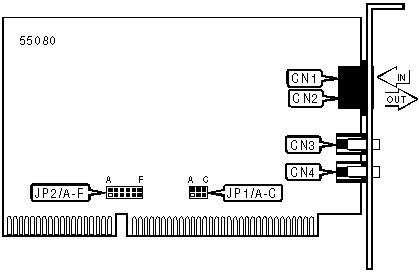
CONNECTIONS | ||||||
|
Function |
Label |
Function |
Label | |||
|
Line in (RJ-11) |
CN1 |
Speaker jack |
CN3 | |||
|
Line out (RJ-11) |
CN2 |
Microphone jack |
CN4 | |||
|
SERIAL PORT ADDRESS | |||
|
Setting |
JP1/A |
JP1/B |
JP1/C |
|
COM1 (3F8h) |
Closed |
Closed |
Closed |
|
COM2 (2F8h) |
Open |
Closed |
Closed |
|
COM3 (3E8h) |
Closed |
Open |
Closed |
|
COM4 (2E8h) |
Open |
Open |
Closed |
|
Plug & play |
Open |
Open |
Open |
|
INTERRUPT | ||||||
|
Setting |
JP2/A |
JP2/B |
JP2/C |
JP2/D |
JP2/E |
JP2/F |
|
IRQ3 |
Closed |
Open |
Open |
Open |
Open |
Open |
|
IRQ4 |
Open |
Closed |
Open |
Open |
Open |
Open |
|
IRQ5 |
Open |
Open |
Closed |
Open |
Open |
Open |
|
IRQ9 |
Open |
Open |
Open |
Closed |
Open |
Open |
|
IRQ10 |
Open |
Open |
Open |
Open |
Closed |
Open |
|
IRQ15 |
Open |
Open |
Open |
Open |
Open |
Closed |
|
Plug & play |
Open |
Open |
Open |
Open |
Open |
Open |
|
SUPPORTED COMMAND SET |
|
Basic AT Commands |
|
AT, ‘+++’, A/ |
|
A, E, H, M, O, V |
|
&C, &G, &T, &W, &Z |
|
S Registers |
|
S0, S1, S2, S3, S4, S5, S6, S7, S8, S9, S10, S11, S12, S18 |
|
Note: See MHI Help File for full command documentation. |
PROPRIETARY AT COMMAND SET
|
BREAK OPTIONS | ||
|
Type: |
Configuration | |
|
Format |
AT [cmds] &Yn [cmds] | |
|
Description: |
Sets the method for break transmission during error-control and ASB connections. | |
|
Command |
Function | |
|
í &Y0 |
Destructive signaling, buffers cleared, does not pass break to DCE | |
|
&Y1 |
Expedited destructive signaling, buffers cleared, immediately send timed break | |
|
&Y2 |
Expedited signaling, break sent out of sequence | |
|
COMMUNICATION PROTOCOLS | |
|
Type: |
Configuration |
|
Format: |
AT [cmds] Bn [cmds] |
|
Description: |
Selects the communication protocol for data calls |
|
Command |
Protocol |
|
í B0 |
ITU-T V.25 answer sequence |
|
B1 |
Answer tone |
|
COMPRESSION | |
|
Type: |
Configuration |
|
Format: |
AT [cmds] &Kn [cmds] |
|
Description: |
Selects data compression |
|
Command |
Function |
|
&K0 |
Data compression disabled |
|
&K1 |
MNP5 and V.42bis enabled if DTE rate is higher than link rate and data compression supported by remote |
|
&K2 |
MNP5 and V.42bis enabled |
|
&K3 |
V.42bis enabled |
|
CONNECT MODE | |
|
Type: |
Configuration |
|
Format: |
AT [cmds] &Mn [cmds] |
|
Description: |
Controls the type of connection the modem will operate in |
|
Command |
Function |
|
&M0 |
Normal mode enabled |
|
í &M4 |
Auto-reliable mode enabled |
|
&M5 |
MNP reliable mode enabled |
|
DATA SET READY (DSR) | |
|
Type: |
Configuration |
|
Format: |
AT [cmds] &Sn [cmds] |
|
Description: |
Selects DSR options |
|
Command |
Function |
|
í &S0 |
DSR forced high |
|
&S1 |
DSR high only while modem is handshaking or connected |
|
DATA TERMINAL READY (DTR) | |
|
Type: |
Configuration |
|
Format: |
AT [cmds] &Dn [cmds] |
|
Description: |
Selects modem response to DTR |
|
Command |
Function |
|
&D0 |
DTR override |
|
&D1 |
DTR toggle causes online command mode |
|
í &D2 |
DTR toggle causes modem to go on-hook |
|
DCE LINE SPEED (MAXIMUM) | |
|
Type: |
Configuration |
|
Format |
AT [cmds] &Nn [cmds] |
|
Description: |
Sets the maximum allowable data exchange rate attempted during handshake process. |
|
Command |
Function |
|
&N1 |
Speed of last connection |
|
&N2 |
300bps |
|
&N3 |
1200bps |
|
&N4 |
2400bps |
|
&N5 |
4800bps |
|
&N6 |
7200bps |
|
&N7 |
9600bps |
|
&N8 |
12.0Kbps |
|
&N9 |
14.4Kbps |
|
&N10 |
16.8Kbps |
|
&N22 |
19.2Kbps |
|
&N12 |
21.6Kbps |
|
&N13 |
24.0Kbps |
|
&N14 |
26.4Kbps |
|
&N15 |
28.8Kbps |
|
&N16 |
31.2Kbps |
|
&N17 |
33.6Kbps |
|
&N18 |
32.0Kbps (X2) |
|
&N19 |
36.0Kbps (X2) |
|
&N20 |
40.0Kbps (X2) |
|
&N21 |
44.0Kbps (X2) |
|
&N22 |
48.0Kbps (X2) |
|
&N23 |
49.3Kbps (X2) |
|
&N24 |
50.7Kbps (X2) |
|
&N25 |
52.0Kbps (X2) |
|
&N26 |
53.3Kbps (X2) |
|
&N27 |
54.7Kbps (X2) |
&N28 |
56.0Kbps (X2) |
|
&N29 |
57.3Kbps (X2) |
|
&N30 |
58.7Kbps (X2) |
&N31 |
60.0Kbps (X2) |
|
&N32 |
61.3Kbps (X2) |
|
DCE LINE SPEED (MINIMUM) | |
|
Type: |
Configuration |
|
Format |
AT [cmds] &Un [cmds] |
|
Description: |
Sets the minimum allowable data exchange rate attempted during handshake process. |
|
Command |
Function |
|
&U1 |
No minimum |
|
&U2 |
300bps |
|
&U3 |
1200bps |
|
&U4 |
2400bps |
|
&U5 |
4800bps |
|
&U6 |
7200bps |
|
&U7 |
9600bps |
|
&U8 |
12.0Kbps |
|
&U9 |
14.4Kbps |
|
&U10 |
16.8Kbps |
|
&U22 |
19.2Kbps |
|
&U12 |
21.6Kbps |
|
&U13 |
24.0Kbps |
|
&U14 |
26.4Kbps |
|
&U15 |
28.8Kbps |
|
&U16 |
31.2Kbps |
|
&U17 |
33.6Kbps |
|
&U18 |
32.0Kbps (X2) |
|
&U19 |
36.0Kbps (X2) |
|
&U20 |
40.0Kbps (X2) |
|
&U21 |
44.0Kbps (X2) |
|
&U22 |
48.0Kbps (X2) |
|
&U23 |
49.3Kbps (X2) |
|
&U24 |
50.7Kbps (X2) |
|
&U25 |
52.0Kbps (X2) |
|
&U26 |
53.3Kbps (X2) |
|
&U27 |
54.7Kbps (X2) |
&U28 |
56.0Kbps (X2) |
|
&U29 |
57.3Kbps (X2) |
|
&U30 |
58.7Kbps (X2) |
&U31 |
60.0Kbps (X2) |
|
&U32 |
61.3Kbps (X2) |
|
DIAL | |
|
Type: |
Immediate |
|
Format: |
AT [cmds] D<#> [cmds] |
|
Description: |
Dials telephone number according to any modifiers included in the string |
|
Note: |
Any combination of modifiers can be used to produce the desired dial functions in sequence. |
|
Command |
Function |
|
DL |
Re-dial last number |
|
DP |
Pulse dialing enabled |
|
DT |
Tone dialing enabled/Pulse dialing disabled |
|
DW |
Dialing resumed following dial tone detection |
|
D, |
Dialing paused for amount of time specified in S8 register |
|
D! |
Flash function initiated. Modem commanded to go off-hook for specified time before returning on-hook. |
|
D/ |
Delays for 125ms before dialing |
|
DR |
Answer mode enabled; originate mode disabled following handshake initiation. |
|
DSn |
Dial stored telephone number n |
|
D@ |
Wait for Quite Answer function enabled. Modem waits until a "quiet answer," a ring-back signal followed by silence up to the time specified in S7, is received prior to executing the rest of the dial string. |
|
D$ |
Wait for prompt tone detection function enabled. Waits for prompt tone for amount of time specified by the S7 command. |
|
D; |
Modem returned to idle state after dialing. The semicolon can only be placed at the end of the dial command. |
|
ERROR CORRECTION RESULT CODES | |
|
Type: |
Configuration |
|
Format: |
AT [cmds] &An [cmds] |
|
Description: |
Selects error correction responses |
|
Command |
Function |
|
&A0 |
ARQ result codes disabled |
|
&A1 |
ARQ to word CONNECT result codes enabled when an error correction connection is made |
|
&A2 |
V.32 indicator added in result codes for calls at or above 4800bps |
|
&A3 |
Protocol response added: /LAPM, /MNP, or NONE and V.42bis/MNP5 |
|
FACTORY DEFAULT PROFILE | |
|
Type: |
Configuration |
|
Format: |
AT [cmds] &Fn [cmds] |
|
Description: |
Sets values in active profile to values found in the default profile |
|
Command |
Function |
|
&F0 |
Load standard factory configuration |
|
&F1 |
Restore factory configuration 1. Hardware flow control |
|
&F2 |
Restore factory configuration 2. Software flow control |
FLOW CONTROL | |
|
Type: |
Configuration |
|
Format: |
AT [cmds] &Hn [cmds] |
|
Description: |
Enables flow control options |
|
Command |
Function |
|
&H0 |
Flow control disabled |
|
&H1 |
RTS to CTS flow control enabled |
|
&H2 |
XON/XOFF flow control enabled |
|
&H3 |
RTS/CTS & XON/XOFF flow control enabled |
|
LIST DISPLAY | |
|
Type: |
Immediate |
|
Format: |
AT [cmds] &$ [cmds] |
|
Description: |
Displays a list of ampersand commands |
|
LOCK SERIAL PORT | |
|
Type: |
Configuration |
|
Format: |
AT [cmds] &Bn [cmds] |
|
Description: |
Sets operation of serial port speed |
|
Command |
Function |
|
&B0 |
Serial speed follows connect speed |
|
í &B1 |
Serial speed locked |
|
&B2 |
In answer mode; serial speed fixed for ARQ calls, variable for non-ARQ calls |
|
PULSE DIALING RATIO | |
|
Type: |
Configuration |
|
Format: |
AT [cmds] &Pn [cmds] |
|
Description: |
Selects pulse dial make/break ratio |
|
Command |
Function |
|
í &P0 |
39/61ms at 10pps (North America) |
|
&P1 |
33/67ms at 10pps (Europe) |
|
REPORT INFORMATION | |
|
Type: |
Immediate |
|
Format: |
AT [cmds] In [cmds] |
|
Description: |
Displays information requested |
|
Command |
Function |
|
I0 |
Reports product code |
|
I1 |
Reports ROM checksum |
|
I2 |
Reports results of RAM self-test |
|
I3 |
Reports product type |
|
I4 |
Reports current modem settings |
|
I5 |
Reports NVRAM settings |
|
I6 |
Reports link diagnostics |
|
I7 |
Reports product confirmation |
|
I8 |
Reserved |
|
I9 |
Reports plug & play information |
|
I10 |
Reserved |
|
I11 |
Reports call statistics |
|
RESTORE PROFILE ON POWER-UP | |
|
Type: |
Configuration |
|
Format: |
AT [cmds] Yn [cmds] |
|
Description: |
Restores a selected profile into the active profile on power-up (hard reset) |
|
Command |
Function |
|
í Y0 |
Restore profile 0 on power-up |
|
Y1 |
Restore profile 1 on power-up |
|
Y2 |
Restore generic factory template (&F0) |
|
Y3 |
Hardware flow control (&F1) |
|
Y4 |
Software flow control (&F2) |
|
RESULT CODES | |
|
Type: |
Configuration |
|
Format: |
AT [cmds] Qn [cmds] |
|
Description: |
Enables modem to send result codes to the DTE |
|
Command |
Function |
|
í Q0 |
Result code sending enabled |
|
Q1 |
Result code sending disabled |
|
Q2 |
Result code sending only in originate mode |
|
Q3 |
Result code sending only in ring mode |
|
RTS | |
|
Type: |
Configuration |
|
Format: |
AT [cmds] &Rn [cmds] |
|
Description: |
Selects RTS |
|
Command |
Function |
|
&R0 |
RTS signal is ignored |
|
í &R1 |
Data is sent to DTE only is RTS in forced high |
|
SELECT CALL PROGRESS RESULT CODES | |
|
Type: |
Configuration |
|
Format: |
AT [cmds] Xn [cmds] |
|
Description: |
Enables selection of tone detection and associated result code format options |
|
Command |
Function |
|
X0 |
Busy and dial tone detection disabled; result codes 0 - 4 enabled. |
|
X1 |
Busy and dial tone detection disabled; result codes 0 - 5 & 10 - 25 enabled. |
|
X2 |
Busy tone detection disabled, dial tone detection enabled; result codes 0 - 6 & 10 - 236 enabled. |
|
X3 |
Busy and dial tone detection disabled; 8 - 236 enabled. |
|
X4 - X6 |
Busy and dial tone detection enabled; extended result codes enabled |
|
SOFT RESET | |
|
Type: |
Immediate |
|
Format: |
AT [cmds] Zn [cmds] |
|
Description: |
Restores modem profiles previously saved in non-volatile RAM using the &W command. |
|
Command |
Function |
|
Z0 |
Restore NVRAM profile selected by ATY command |
|
Z1 |
Restore NVRAM profile 0 |
|
Z2 |
Restore NVRAM profile 1 |
|
Z3 |
Restore factory default profile 0 (&F0) |
|
Z4 |
Restore factory default profile 1 (&F1) |
|
Z5 |
Restore factory default profile 2 (&F2) |
|
SPEAKER VOLUME | |
|
Type: |
Configuration |
|
Format: |
AT [cmds] Ln [cmds] |
|
Description: |
Controls speaker volume |
|
Command |
Function |
|
L0 |
Low volume setting |
|
L1 |
Low volume setting |
|
í L2 |
Medium volume setting |
|
L3 |
Highest volume setting |
|
XON/XOFF PASS-THROUGH | |
|
Type: |
Configuration |
|
Format: |
AT [cmds] &In [cmds] |
|
Description: |
Selects whether XON/XOFF signals are sent to remote modem |
|
Command |
Function |
|
í &I0 |
XON/XOFF signals trapped by local modem |
|
&I1 |
XON/XOFF passed through local modem and remote |
|
&I2 |
XON/XOFF passed through local modem only |
S(status) -REGISTERS
|
ANSWER TONES, DEFAULT TIMES, AND CONNECTION LIMITING | ||
|
Type: |
Register | |
|
Format |
AT [cmds] S28=n [cmds] | |
|
Description: |
Controls answer tones, connections, and time specified | |
|
Command |
Function | |
|
S28=0 |
Eliminates V.32 answer tones for a faster connection | |
|
S28=8 |
All default times are in 1sec units | |
|
S28=255 |
Connections disabled except V.32 9600bps | |
|
BIT-MAPPED REGISTER S27 | |||
|
Format: |
AT [cmds] S27=n [cmds] | ||
|
Range: |
0-255 | ||
|
Description: |
Select modulations and error correction flags | ||
|
Bit |
Value |
Function | |
|
0 |
0 1 |
V.21/Bell 103 mode disabled V.21/Bell 103 mode enabled | |
|
1 |
0 1 |
Unencoded modulation in V.32 mode disabled Unencoded modulation in V.32 mode enabled | |
|
2 |
0 1 |
V.32 modulation enabled V.32 modulation disabled | |
|
3 |
0 1 |
2100Hz answer tone enabled 2100Hz answer tone enabled | |
|
4 |
0 1 |
V.23 fallback mode disabled V.23 fallback mode enabled | |
|
5 |
0 1 |
V.32bis mode enabled V.32bis mode disabled | |
|
6 |
0 |
Reserved | |
|
7 |
0 1 |
Software compatibility mode disabled Software compatibility mode enabled | |
|
BIT-MAPPED REGISTER S32 | |||
|
Format: |
AT [cmds] S32=n [cmds] | ||
|
Range: |
0-255 | ||
|
Description: |
Select modulations and call control flags | ||
|
Bit |
Value |
Function | |
|
0 |
0 1 |
V.8 call indicate disabled V.8 call indicate enabled | |
|
1 |
0 1 |
V.8 mode disabled V.8 mode enabled | |
|
2 |
0 1 |
V.FC modulation enabled V.FC modulation disabled | |
|
3 |
0 1 |
V.34 modulation enabled V.34 modulation disabled | |
|
4 |
0 1 |
V.34+ modulation enabled V.34+ modulation disabled | |
|
5 |
0 1 |
X2 modulation enabled X2 modulation disabled | |
|
6 |
0 1 |
V.90 modulation enabled V.90 modulation disabled | |
|
7 |
0 |
Reserved | |
|
BIT-MAPPED REGISTER S33 | |||
|
Format: |
AT [cmds] S33=n [cmds] | ||
|
Range: |
0-255 | ||
|
Description: |
Enables/disables symbol rates | ||
|
Bit |
Value |
Function | |
|
0 |
0 1 |
2400 symbol rate enabled 2400 symbol rate disabled | |
|
1 |
0 1 |
2743 symbol rate enabled 2743 symbol rate disabled | |
|
2 |
0 1 |
2800 symbol rate enabled 2800 symbol rate disabled | |
|
3 |
0 1 |
3000 symbol rate enabled 3000 symbol rate disabled | |
|
4 |
0 1 |
3200 symbol rate enabled 3200 symbol rate disabled | |
|
5 |
0 1 |
3429 symbol rate enabled 3429 symbol rate disabled | |
|
6 |
0 |
Reserved | |
|
7 |
0 1 |
2400 symbol rate enabled 2400 symbol rate disabled | |
|
BIT-MAPPED REGISTER S34 | |||
|
Format: |
AT [cmds] S34=n [cmds] | ||
|
Range: |
0-255 | ||
|
Description: |
Controls trellis coding options | ||
|
Bit |
Value |
Function | |
|
0 |
0 1 |
8S-2D trellis encoding enabled 8S-2D trellis encoding disabled | |
|
1 |
0 1 |
16S-4D trellis encoding enabled 16S-4D trellis encoding disabled | |
|
2 |
0 1 |
32S-2D trellis encoding enabled 32S-2D trellis encoding disabled | |
|
3 |
0 1 |
64S-4D trellis encoding enabled 64S-4D trellis encoding disabled | |
|
4 |
0 1 |
Non-linear coding enabled Non-linear coding disabled | |
|
5 |
0 1 |
TX level deviation enabled TX level deviation disabled | |
|
6 |
0 1 |
Pre-emphasis enabled Pre-emphasis disabled | |
|
7 |
0 1 |
Pre-coding enabled Pre-coding disabled | |
|
BIT-MAPPED REGISTER S41 | |||
|
Format: |
AT [cmds] S41=n [cmds] | ||
|
Range: |
0-255 | ||
|
Description: |
Controls trellis coding options | ||
|
Bit |
Value |
Function | |
|
0, 1 |
0000 0001 1000 |
Full-duplex speaker mode Half-duplex speaker mode Message waiting | |
|
7-2 |
0 |
Reserved | |
|
BREAK CHARACTER LENGTH | |
|
Type: |
Register |
|
Format |
AT [cmds] S21=n [cmds] |
|
Range: |
0-255 |
|
Unit: |
10ms |
|
Description: |
Sets the length of break characters sent from modem to DTE in MNP or V.42 mode |
|
DCE LINE SPEED (PARTIALLY BIT-MAPPED) | |||
|
Type: |
Register | ||
|
Format |
AT [cmds] S35=n [cmds] | ||
|
Description: |
Sets the maximum allowable data exchange rate attempted during handshake process and limits x2 back channel operation | ||
|
Command |
Function | ||
|
S35=0 |
No back channel rate | ||
|
S35=1 |
28.8Kbps | ||
|
S35=2 |
26.4Kbps | ||
|
S35=3 |
24.0Kbps | ||
|
S35=4 |
21.6Kbps | ||
|
S35=5 |
19.2Kbps | ||
|
S35=6 |
16.8Kbps | ||
|
S35=7 |
14.4Kbps | ||
|
Bit |
Value |
Function | |
|
3 |
í 0 1 |
X2 server operation disabled X2 server operation enabled | |
|
4 |
í 0 1 |
A /m law operation disabled A /m law operation enabled | |
|
5 |
í 0 1 |
A /m law detection enabled A /m law detection disabled | |
|
6 |
í 0 1 |
Reduced power enabled Reduced power disabled | |
|
7 |
0 |
Reserved | |
|
DTR IGNORE TIME ON CONNECT | |
|
Type: |
Register |
|
Format |
AT [cmds] S25=n [cmds] |
|
Range: |
0-255 |
|
Unit: |
.01 second |
|
Description: |
Sets time modem waits to hang-up when DTR signal shuts off |
Note: This is the function of this register when &D2 is set. | |
|
FLOW CONTROL CHARACTER - XOFF | |
|
Type: |
Register |
|
Format: |
AT [cmds] S23=n [cmds] |
|
Range: |
0-255 |
|
Unit: |
ASCII |
|
Description: |
Sets the character used to represent XOFF |
|
FLOW CONTROL CHARACTER - XON | |
|
Type: |
Register |
|
Format: |
AT [cmds] S22=n [cmds] |
|
Range: |
0-255 |
|
Unit: |
ASCII |
|
Description: |
Sets the character used to represent XON |
|
INACTIVITY TIMER | |
|
Type: |
Register |
|
Format |
AT [cmds] S19=n [cmds] |
|
Range: |
0-255 |
|
Unit: |
1min |
|
Description: |
Maximum duration of DTE and DCE inactivity allowed prior to initiating hang-up process. |
Note: S19=0 disables the timer and allows indefinite inactivity. | |