BROOKTROUT TECHNOLOGY, INC.
TR114-I4C, TR114-I4D, TR114-I4L (REV. 5)
|
Card Type |
Telephony |
|
Processor |
NS32FX16/NS32FX164 |
|
Processor Speed |
25MHz |
|
Maximum Onboard Memory |
1MB DRAM |
|
I/O Options |
Line out (4) |
|
Data Bus |
8/16-bit ISA |
|
Line Type |
DID, Loop-start |
|
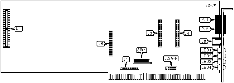
CONNECTIONS | |||
|
Function |
Label |
Function |
Label |
|
Loop-start daughterboard header |
J3 |
Lines 1 and 2 |
PJ1 |
|
Loop-start daughterboard header |
J4 |
Lines 3 and 4 |
PJ2 |
|
DID daughterboard header |
J5 |
Loop-start chip |
U1 |
|
48V DC power in |
J8 | ||
|
USER CONFIGURABLE SETTINGS | |||
|
Setting |
Label |
Position | |
| » |
Internal self-test disabled |
SW1/1 |
Off |
|
Internal self-test enabled |
SW1/1 |
On | |
| » |
Interrupt pull-up resistor enabled |
SW1/2 |
On |
|
Interrupt pull-up resistor disabled |
SW1/2 |
Off | |
|
Note:SW1/2 should be on for only one TR112 or TR114 per system. | |||
|
INTERRUPT | ||||||||
|
Setting |
J1 |
J2/A |
J2/B |
J2/C |
J2/D |
J2/E |
J2/F | |
|
IR/FONT> |
Open |
Open |
Open |
Open |
Open |
Open |
Closed | |
|
IRQ3 |
Open |
Closed |
Open |
Open |
Open |
Open |
Open | |
|
IRQ4 |
Open |
Open |
Closed |
Open |
Open |
Open |
Open | |
| » |
IRQ5 |
Open |
Open |
Open |
Closed |
Open |
Open |
Open |
|
IRQ6 |
Open |
Open |
Open |
Open |
Closed |
Open |
Open | |
|
IRQ7 |
Open |
Open |
Open |
Open |
Open |
Closed |
Open | |
|
IRQ10 |
Pins 9 & 10 closed |
Open |
Open |
Open |
Open |
Open |
Open | |
|
IRQ11 |
Pins 7 & 8 closed |
Open |
Open |
Open |
Open |
Open |
Open | |
|
IRQ12 |
Pins 5 & 6 closed |
Open |
Open |
Open |
Open |
Open |
Open | |
|
IRQ14 |
Pins 3 & 4 closed |
Open |
Open |
Open |
Open |
Open |
Open | |
|
IRQ15 |
Pins 1 & 2 closed |
Open |
Open |
Open |
Open |
Open |
Open | |
|
BASE I/O ADDRESS | |||||||
|
Setting |
SW1/3 |
SW1/4 |
SW1/5 |
SW1/6 |
SW1/7 |
SW1/8 | |
|
000h |
On |
On |
On |
On |
On |
On | |
|
010h |
Off |
On |
On |
On |
On |
On | |
|
020h |
On |
Off |
On |
On |
On |
On | |
|
030h |
Off |
Off |
On |
On |
On |
On | |
|
040h |
On |
On |
Off |
On |
On |
On | |
| » |
260h |
On |
Off |
Off |
On |
On |
Off |
|
3B0h |
Off |
Off |
On |
Off |
Off |
Off | |
|
3C0h |
On |
On |
Off |
Off |
Off |
Off | |
|
3D0h |
Off |
On |
Off |
Off |
Off |
Off | |
|
3E0h |
On |
Off |
Off |
Off |
Off |
Off | |
|
3F0h |
Off |
Off |
Off |
Off |
Off |
Off | |
|
Note: A total of 64 base address settings are available. The switches are a binary representation of the decimal memory addresses. SW1/8 is the Most Significant Bit and switch SW1/3 is the Least Significant Bit. The switches have the following decimal values: SW1/8=512, SW1/7=256, SW1/6=128, SW1/5=64, SW1/4=32, SW1/3=16. Turn off the switches and add the values of the switches that are off to obtain the correct memory address. (Off=1, On=0) | |||||||
|
DIAGNOSTIC LED(S) | |||
|
LED |
Color |
Status |
Function |
|
LED1 |
Red |
N/A |
Line 1 |
|
LED2 |
Red |
N/A |
Line 2 |
|
LED3 |
Red |
N/A |
Line 3 |
|
LED4 |
Red |
N/A |
Line 4 |
|
Note:The functions of the LEDs depend on firmware settings. | |||