BOCA RESEARCH, INC.
SUPER MODEM 2400 (EXT.)
|
Modem Type |
Data (synchronous/asynchronous) |
|
Maximum Data Rate |
2400bps |
|
Data Bus |
External |
|
Data Modulation Protocol |
Bell 103A/212A ITU-T V.21, V.22, V.22bis |
|
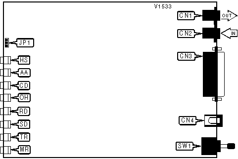
CONNECTIONS | |||
|
Purpose |
Location |
Purpose |
Location |
|
Line out |
CN1 |
DC power |
CN4 |
|
Line in |
CN2 |
Power switch |
SW1 |
|
RS-232/422 |
CN3 | ||
|
SMART/DUMB MODE | |
|
Setting |
JP1 |
| » Smart mode |
Closed |
| Dumb mode |
Open |
|
Note: Manufacturer’s documentation does not specify pin assignments corresponding to dumb/smart mode settings. | |
|
DIAGNOSTIC LED(S) | |||
|
LED |
Color |
Status |
Condition |
|
HS |
Red |
On |
Modem connected at 2400bps |
|
HS |
Red |
Off |
Modem not connected at 2400bps |
|
AA |
Red |
On |
Auto-answer enabled |
|
AA |
Red |
Off |
Auto-answer disabled |
|
AA |
Red |
Blinking |
Phone is ringing |
|
CD |
Red |
On |
Carrier signal detected |
|
CD |
Red |
Off |
Carrier signal not detected |
|
OH |
Red |
On |
Modem is off-hook |
|
OH |
Red |
Off |
Modem is on-hook |
|
RD |
Red |
On |
Modem is receiving data |
|
RD |
Red |
Off |
Modem is not receiving data |
|
SD |
Red |
On |
Modem is transmitting data |
|
SD |
Red |
Off |
Modem is not transmitting data |
|
TR |
Red |
On |
DTR signal is high |
|
TR |
Red |
Off |
DTR signal is low |
|
MR |
Red |
On |
Power is on |
|
MR |
Red |
Off |
Power is off |
Proprietary AT Command Set
|
BIT-MAPPED REGISTER S14 | |||
|
Format |
AT [cmds] S14=n [cmds] | ||
|
Example: |
ATS14=138 <CR> | ||
|
Default: |
138 | ||
|
Range: |
0-190 | ||
|
Unit: |
Bit-mapped | ||
|
Description: |
Controls echo, result codes, result code display, smart/dumb mode, dial mode, and answer/originate mode. | ||
|
Bit | Value |
Function | |
|
0 | 0 |
Not used. | |
|
1 | 0 » 1 |
Command echo disabled. Command echo enabled. | |
|
2 | » 0 1 |
Result codes enabled. Result codes disabled. | |
|
3 | 0 » 1 |
Display result codes in numeric format. Display result codes in verbose format. | |
|
4 | » 0 1 |
Smart mode. Dumb mode | |
|
5 | » 0 1 |
Tone dial enabled. Pulse dial enabled. | |
|
6 | 0 |
Not used. | |
|
7 | 0 » 1 |
Answer mode enabled. Originate mode enabled. | |
|
Note: Bit 4 is not used, in the Internal Super Modem 2400. | |||
|
BIT-MAPPED REGISTER S21 | |||
|
Format |
AT [cmds] S21=n [cmds] | ||
|
Example: |
ATS21=56 <CR> | ||
|
Default: |
56 | ||
|
Range: |
0 - 189 | ||
|
Unit: |
Bit-mapped | ||
|
Description: |
Selects jack type, CTS signal, low DTR action, DCD signal, and the Long Space Disconnect function. | ||
|
Bit | Value |
Function | |
|
0 | » 0 1 |
Selects RJ-11, RJ-41S, or RJ45S jack. Selects RJ-12 or RJ-13 jack. | |
|
1 | 0 |
Not used. | |
|
2 | » 0 1 |
CTS follows RTS. CTS forced high. | |
|
4, 3 | 00 01 10 » 11 |
DTR signal ignored. Modem goes to command mode on low DTR. Modem disconnects on low DTR. Auto-Answer is disabled. Modem is initialized on low DTR. | |
|
5 | 0 » 1 |
DCD forced high. DCD normal. | |
|
6 | 0 |
Not used. | |
|
7 | » 0 1 |
Long Space Disconnect function disabled. Long Space Disconnect function enabled. | |
|
Note: Bit 2 is not used, in the Internal Super Modem 2400. | |||
|
BIT-MAPPED REGISTER S22 | |||
|
Format |
AT [cmds] S22=n [cmds] | ||
|
Example: |
ATS22=5 <CR> | ||
|
Default: |
5 | ||
|
Range: |
0-126 | ||
|
Unit: |
Bit-mapped | ||
|
Description: |
Controls speaker volume and controls, and limits results codes. | ||
|
Bit | Value |
Function | |
|
1, 0 | 01 » 10 11 |
On volume. Medium level volume. High level volume. | |
|
3, 2 | 00 » 01 10 11 |
Speaker off. Speaker off on carrier. Speaker always on. Speaker on during handshake. | |
|
6, 5, 4 | » 000 100 101 110 111 |
Basic result codes only enabled. Basic and connection speed result codes enabled. Basic and connection speed result codes and dialtone detection enabled. All result codes except dialtone detection enabled. All result codes enabled. | |
|
7 | » 0 1 |
39/61ms at 10pps (North America) 33/67ms at 10pps (Europe) | |
|
BIT-MAPPED REGISTER S23 | |||
|
Format |
AT [cmds] S23=n [cmds] | ||
|
Example: |
ATS23=54 <CR> | ||
|
Default: |
54 | ||
|
Range: |
0-183 | ||
|
Unit: |
Bit-mapped | ||
|
Description: |
Grants/denies remote digital loopback, controls DTE rate and parity, and sets guard tone. | ||
|
Bit | Value |
Function | |
|
0 | » 0 1 |
Remote digital loopback denied. Remote digital loopback allowed. | |
|
2, 1 | 00 10 » 11 |
Sets serial port speed to 0-300bps. Sets serial port speed to 1200bps. Sets serial port speed to 2400bps. | |
|
3 | 0 |
Not used. | |
|
5,4 | 00 01 10 » 11 |
Parity even. Space parity. Parity odd. No Parity. | |
|
7, 6 | » 00 01 10 |
Guard tone disabled. Guard tone disabled. Guard tone 1800Hz enabled. | |
|
BIT-MAPPED REGISTER S27 | |||
|
Format |
AT [cmds] S27=n [cmds] | ||
|
Example: |
AT S27=64 <CR> | ||
|
Default: |
64 | ||
|
Range: |
0 - 103 | ||
|
Unit: |
Bit-mapped | ||
|
Description: |
Selects sync/async mode, Line type, internal clock, and ITU-T/Bell modes. | ||
|
Bit | Value |
Function | |
|
1, 0 | » 00 01 10 11 |
Asynchronous mode. Synchronous command mode and synchronous connect mode. Synchronous command mode and synchronous connect mode, DTR dialing enabled. Manual originating a synchronous call. | |
|
2 | » 0 1 |
Dial up line. Leased line. | |
|
3 | 0 |
Not used. | |
|
5, 4 | » 00 01 10 |
Internal DTE transmit clock source. External DTE transmit clock source. Slave DTE transmit clock source. | |
|
6 | 0 » 1 |
CCITT mode. Bell mode. | |
|
TEST MODES | |||
|
Format |
AT [cmds] S16=n [cmds] | ||
|
Example: |
ATS16=0 <CR> | ||
|
Default: |
0 | ||
|
Range: |
0-125 | ||
|
Unit: |
Bit-mapped | ||
|
Description: |
Controls loopback tests, analog, digital, remote digital, and self tests. | ||
|
Bit |
Value |
Function | |
|
0 | » 0 1 |
Local analog loopback not in progress. Local analog loopback in progress. | |
|
1 | 0 |
Not used. | |
|
2 | » 0 1 |
Local digital loopback not in progress. Local digital loopback in progress. | |
|
3 | » 0 1 |
Modem not in remote digital loopback. Remote digital loopback in progress. | |
|
4 | » 0 1 |
Remote digital loopback not requested. Remote digital loopback requested. | |
|
5 | » 0 1 |
Remote digital loopback w/ self-test not in progress. Remote digital loopback w/ self-test in progress. | |
|
6 | » 0 1 |
Local analog loopback w/ self-test not in progress. Local analog loopback w/ self-test in progress. | |