SYSTRAN CORPORATION
SCRAMNET+ VME3U
|
NIC Type |
Proprietary |
|
Chipset |
Systran Corporation |
|
Maximum Onboard Memory |
8MB DRAM |
|
I/O Options |
Bypass connector |
|
Network Transfer Rate |
150Mbps |
|
Data Bus |
VME |
|
Topology |
Linear Bus/Ring |
|
Wire Type |
RG-58A/U 50ohm coaxial Fiber optic cable |
|
Boot ROM |
Not available |
|
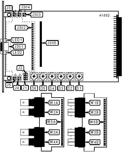
CONNECTIONS | |||
|
Function |
Label |
Function |
Label |
|
Auxiliary connector (see pinout below) |
J1 |
Fiber optic ST receive connector 1 |
W1B |
|
Auxiliary connector (see pinout below) |
J2 |
RG-58A/U 50ohm coaxial receive connector 2 |
W2A |
|
Bypass connector |
J301 |
Fiber optic ST receive connector 2 |
W2B |
|
Daughterboard header |
J302 |
RG-58A/U 50ohm coaxial transmit connector 1 |
W3A |
|
Memory card header |
J305 |
Fiber optic ST transmit connector 1 |
W3B |
|
RG-58A/U 50ohm coaxial receive connector 1 |
W1A |
RG-58A/U 50ohm coaxial transmit connector 2 |
W4A |
|
Fiber optic ST transmit connector 2 |
W4B |
Header to main board J302 |
W5B |
|
Header to main board J302 |
W5A |
Header to main board J302 |
W5C |
|
J1 PINOUT | |||
|
Function |
Pin |
Function |
Pin |
|
Not used |
1 |
External LED (see LED2 in table) |
3 |
|
External LED (see LED1 in table) |
2 |
Signal common |
4 |
|
J2 PINOUT | |||
|
Function |
Pin |
Function |
Pin |
|
Not used |
1 |
External LED (see LED3 in table) |
3 |
|
Message waiting signal |
2 |
Signal common |
4 |
|
USER CONFIGURABLE SETTINGS | |||
|
Setting |
Label |
Position | |
| » |
Chassis ground connected to signal ground |
J3 |
Pins 2 & 4 closed |
|
Chassis ground not connected to signal ground |
J3 |
Pins 1 & 3 closed | |
| » |
EEPROM write protect enabled |
J303 |
Pins 1 & 3 closed |
|
EEPROM write protect disabled |
J303 |
Pins 2 & 4 closed | |
| » |
EEPROM read protect enabled |
J304 |
Pins 1 & 3 closed |
|
EEPROM read protect disabled |
J304 |
Pins 2 & 4 closed | |
| » |
Variable length packets disabled |
J4 |
Pins 1 & 3 closed |
|
Variable length packets enabled |
J4 |
Pins 2 & 4 closed | |
| » |
Card is not software compatible with ScramNET Classic cards |
J5 |
Pins 1 & 3 closed |
|
Card is software compatible with ScramNET Classic cards |
J5 |
Pins 2 & 4 closed | |
| » |
Control/Status register addressing is 16 bits wide |
S6 |
Position 6 |
|
Control/Status register addressing is 24 bits wide |
S6 |
Position A | |
|
CONTROL/STATUS REGISTER ADDRESS SELECTION |
|
A total of 262,144 address settings are available. Switches S1 through S5 set the hexadecimal memory address. SW1 is the Most Significant Nibble and switch SW5 is the Least Significant Nibble, though the bottom two bits of SW5 are always 0. The switches have the following decimal weight values: SW1=1,048,576, SW2=65,536, SW3=4,096, SW4=256, SW5=16. Set the switches, multiply the number on the switch by its weight value, add the values obtained for each switch, and round down to the nearest multiple of 64 to obtain the correct memory address. |
|
DIAGNOSTIC LED(S) | |||
|
LED |
Color |
Status |
Condition |
|
LED1 |
Green |
On |
Network connection is good |
|
LED1 |
Green |
Off |
Network connection is broken |
|
LED2 |
Green |
On |
Carrier signal is detected |
|
LED2 |
Green |
Off |
Carrier signal is not detected |
|
LED3 |
N/A |
On |
Error condition detected |
|
LED3 |
N/A |
Off |
Error condition not detected |
|
Note:LED3 is only available via connector J2. | |||