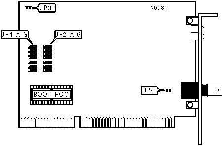
KATRON TECHNOLOGIES, INC.
ET16TB/5B
|
NIC Type |
Ethernet |
|
Transfer Rate |
10Mbps |
|
Data Bus |
16-bit ISA |
|
Topology |
Linear Bus |
|
Wiring Type |
RG-58A/U 50ohm coaxial |
|
Boot ROM |
Available |

|
CONFIGURATION TYPE SELECTION | ||
|
Type |
JP1 A | |
| » |
Hardware |
Pins 1 & 2 closed |
|
Software |
Pins 2 & 3 closed | |
|
CABLE TYPE SELECTION | ||
|
Cable Type |
JP2 C | |
| » |
RG-58A/U 50ohm coaxial |
Pins 2 & 3 closed |
|
Unshielded twisted pair |
N/A | |
|
BASE I/O ADDRESS SELECTION | ||||
|
Address |
JP1 B |
JP1 C |
JP1 D | |
| » |
300h |
Pins 1 & 2 closed |
Pins 1 & 2 closed |
Pins 1 & 2 closed |
|
240h |
Pins 1 & 2 closed |
Pins 2 & 3 closed |
Pins 1 & 2 closed | |
|
280h |
Pins 2 & 3 closed |
Pins 2 & 3 closed |
Pins 1 & 2 closed | |
|
2C0h |
Pins 1 & 2 closed |
Pins 1 & 2 closed |
Pins 2 & 3 closed | |
|
320h |
Pins 2 & 3 closed |
Pins 1 & 2 closed |
Pins 2 & 3 closed | |
|
340h |
Pins 1 & 2 closed |
Pins 2 & 3 closed |
Pins 2 & 3 closed | |
|
360h |
Pins 2 & 3 closed |
Pins 2 & 3 closed |
Pins 2 & 3 closed | |
|
INTERRUPT SELECTION | ||||
|
IRQ |
JP1 E |
JP1 F |
JP1 G | |
| » |
3 |
Pins 1 & 2 closed |
Pins 1 & 2 closed |
Pins 1 & 2 closed |
|
2 |
Pins 2 & 3 closed |
Pins 1 & 2 closed |
Pins 1 & 2 closed | |
|
4 |
Pins 1 & 2 closed |
Pins 2 & 3 closed |
Pins 1 & 2 closed | |
|
5 |
Pins 2 & 3 closed |
Pins 2 & 3 closed |
Pins 1 & 2 closed | |
|
10 |
Pins 1 & 2 closed |
Pins 1 & 2 closed |
Pins 2 & 3 closed | |
|
11 |
Pins 2 & 3 closed |
Pins 1 & 2 closed |
Pins 2 & 3 closed | |
|
12 |
Pins 1 & 2 closed |
Pins 2 & 3 closed |
Pins 2 & 3 closed | |
|
15 |
Pins 2 & 3 closed |
Pins 2 & 3 closed |
Pins 2 & 3 closed | |
|
SHARED RAM CONFIGURATION | ||
|
Mode |
JP2 A | |
| » |
I/O mode |
Pins 1 & 2 closed |
|
Shared RAM mode |
Pins 2 & 3 closed | |
|
ROM ADDRESS | |||||
|
Address |
JP2 D |
JP2 E |
JP2 F |
JP2 G | |
| » |
Disabled |
Pins 1 & 2 closed |
Pins 1 & 2 closed |
Pins 1 & 2 closed |
Pins 1 & 2 closed |
|
C0000 |
Pins 1 & 2 closed |
Pins 2 & 3 closed |
Pins 1 & 2 closed |
Pins 1 & 2 closed | |
|
C4000 |
Pins 2 & 3 closed |
Pins 2 & 3 closed |
Pins 1 & 2 closed |
Pins 1 & 2 closed | |
|
C8000 |
Pins 1 & 2 closed |
Pins 1 & 2 closed |
Pins 2 & 3 closed |
Pins 1 & 2 closed | |
|
CC000 |
Pins 2 & 3 closed |
Pins 1 & 2 closed |
Pins 2 & 3 closed |
Pins 1 & 2 closed | |
|
D0000 |
Pins 1 & 2 closed |
Pins 2 & 3 closed |
Pins 2 & 3 closed |
Pins 1 & 2 closed | |
|
D4000 |
Pins 2 & 3 closed |
Pins 2 & 3 closed |
Pins 2 & 3 closed |
Pins 1 & 2 closed | |
|
D8000 |
Pins 1 & 2 closed |
Pins 1 & 2 closed |
Pins 1 & 2 closed |
Pins 2 & 3 closed | |
|
DC000 |
Pins 2 & 3 closed |
Pins 1 & 2 closed |
Pins 1 & 2 closed |
Pins 2 & 3 closed | |
|
FAST I/O CONFIGURATION | ||
|
Setting |
JP2 B | |
| » |
Disabled |
Pins 1 & 2 closed |
|
Enabled |
Pins 2 & 3 closed | |
|
FACTORY CONFIGURED - DO NOT ALTER | |
|
Jumper/Switch |
Position |
|
JP3 |
N/A |
|
JP4 |
N/A |

|
DIAGNOSTIC LED(S) | ||
|
LED |
Status |
Condition |
|
LED1 |
On |
Network connection is good |
|
LED1 |
Off |
Network connection is broken |
|
LED2 |
On |
Polarity reversed |
|
LED2 |
Off |
Polarity not reversed |
|
LED3 |
Blink |
Data is being transmitted/received |
|
LED3 |
On |
Network card failure |
|
LED3 |
Off |
Data is not being transmitted/received |
|
LED4 |
On |
Network collision is occuring |
|
LED4 |
Off |
Network collision is not occuring |