BLACK BOX CORPORATION
5210E, LE031-C
|
NIC Type |
Ethernet |
|
Transfer Rate |
10Mbps |
|
Data Bus |
8-bit ISA |
|
Topology |
Linear Bus |
|
Wiring Type |
RG-58A/U 50ohm coaxial AUI transceiver via DB-15 port |
|
Boot ROM |
Available |
|
INTERRUPT REQUEST |
|||||||
|
IRQ |
JP1 |
JP2 |
JP3 |
JP4 |
JP5 |
JP6 |
|
|
» |
2 |
Closed |
Open |
Open |
Open |
Open |
Open |
|
|
3 |
Open |
Closed |
Open |
Open |
Open |
Open |
|
|
4 |
Open |
Open |
Closed |
Open |
Open |
Open |
|
|
5 |
Open |
Open |
Open |
Closed |
Open |
Open |
|
|
6 |
Open |
Open |
Open |
Open |
Closed |
Open |
|
|
7 |
Open |
Open |
Open |
Open |
Open |
Closed |
|
I/O BASE ADDRESS |
|||||||
|
Address |
JP7 |
JP8 |
JP9 |
JP10 |
JP11 |
JP12 |
|
|
|
200h |
Pins 2 & 3 |
Pins 2 & 3 |
Pins 2 & 3 |
Pins 2 & 3 |
Pins 2 & 3 |
Pins 2 & 3 |
|
|
208h |
Pins 2 & 3 |
Pins 2 & 3 |
Pins 2 & 3 |
Pins 2 & 3 |
Pins 2 & 3 |
Pins 1 & 2 |
|
|
210h |
Pins 2 & 3 |
Pins 2 & 3 |
Pins 2 & 3 |
Pins 2 & 3 |
Pins 1 & 2 |
Pins 2 & 3 |
|
|
218h |
Pins 2 & 3 |
Pins 2 & 3 |
Pins 2 & 3 |
Pins 2 & 3 |
Pins 1 & 2 |
Pins 1 & 2 |
|
|
350h |
Pins 1 & 2 |
Pins 2 & 3 |
Pins 1 & 2 |
Pins 2 & 3 |
Pins 1 & 2 |
Pins 2 & 3 |
|
|
358h |
Pins 1 & 2 |
Pins 2 & 3 |
Pins 1 & 2 |
Pins 2 & 3 |
Pins 1 & 2 |
Pins 1 & 2 |
|
» |
360h |
Pins 1 & 2 |
Pins 2 & 3 |
Pins 1 & 2 |
Pins 1 & 2 |
Pins 2 & 3 |
Pins 2 & 3 |
|
|
368h |
Pins 1 & 2 |
Pins 2 & 3 |
Pins 1 & 2 |
Pins 1 & 2 |
Pins 2 & 3 |
Pins 1 & 2 |
|
|
370h |
Pins 1 & 2 |
Pins 2 & 3 |
Pins 1 & 2 |
Pins 1 & 2 |
Pins 1 & 2 |
Pins 2 & 3 |
|
|
3E0h |
Pins 1 & 2 |
Pins 1 & 2 |
Pins 1 & 2 |
Pins 1 & 2 |
Pins 2 & 3 |
Pins 2 & 3 |
|
|
3E8h |
Pins 1 & 2 |
Pins 1 & 2 |
Pins 1 & 2 |
Pins 1 & 2 |
Pins 2 & 3 |
Pins 1 & 2 |
|
|
3F0h |
Pins 1 & 2 |
Pins 1 & 2 |
Pins 1 & 2 |
Pins 1 & 2 |
Pins 1 & 2 |
Pins 2 & 3 |
|
|
3F8h |
Pins 1 & 2 |
Pins 1 & 2 |
Pins 1 & 2 |
Pins 1 & 2 |
Pins 1 & 2 |
Pins 1 & 2 |
|
Note: Pins designated should be in the closed position. A full range of I/O addresses are available, in increments of 8h, from 200h to 3F0h for a total of 64 addresses. The 12 examples given are taken from the beginning (first four), the middle (middle four), and the end (last four) of the 64 addresses. To figure out the correct configuration for the I/O address you wish to use, subtract 200h from the address, divide the remainder by 08h, and convert the quotient to a 6-digit binary number. The binary number will represent the setting of each jumper. Each 0 represents pins 2 & 3 closed while each 1 represents pins 1 & 2 Closed. JP7 is the most significant bit (MSB) and JP12 is the least significant bit (LSB). For example, If the desired address is 228h; 228h - 200h = 28h, 28h /08h = 05h, 05h = 000101b, then the setting should be: |
|||||||
|
|
Address |
JP7 |
JP8 |
JP9 |
JP10 |
JP11 |
JP12 |
|
|
228h |
Pins 2 & 3 |
Pins 2 & 3 |
Pins 2 & 3 |
Pins 1 & 2 |
Pins 2 & 3 |
Pins 1 & 2 |
|
BASE MEMORY ADDRESS |
|||||
|
Address |
JP13 |
JP14 |
JP15 |
JP16 |
|
|
» |
C0000h |
Pins 2 & 3 Closed |
Pins 2 & 3 Closed |
Pins 2 & 3 Closed |
Pins 2 & 3 Closed |
|
|
C4000h |
Pins 2 & 3 Closed |
Pins 2 & 3 Closed |
Pins 2 & 3 Closed |
Pins 1 & 2 Closed |
|
|
C8000h |
Pins 2 & 3 Closed |
Pins 2 & 3 Closed |
Pins 1 & 2 Closed |
Pins 2 & 3 Closed |
|
|
CC000h |
Pins 2 & 3 Closed |
Pins 2 & 3 Closed |
Pins 1 & 2 Closed |
Pins 1 & 2 Closed |
|
|
D0000h |
Pins 2 & 3 Closed |
Pins 1 & 2 Closed |
Pins 2 & 3 Closed |
Pins 2 & 3 Closed |
|
|
D4000h |
Pins 2 & 3 Closed |
Pins 1 & 2 Closed |
Pins 2 & 3 Closed |
Pins 1 & 2 Closed |
|
|
D8000h |
Pins 2 & 3 Closed |
Pins 1 & 2 Closed |
Pins 1 & 2 Closed |
Pins 2 & 3 Closed |
|
|
DC000h |
Pins 2 & 3 Closed |
Pins 1 & 2 Closed |
Pins 1 & 2 Closed |
Pins 1 & 2 Closed |
|
|
E0000h |
Pins 1 & 2 Closed |
Pins 2 & 3 Closed |
Pins 2 & 3 Closed |
Pins 2 & 3 Closed |
|
|
E4000h |
Pins 1 & 2 Closed |
Pins 2 & 3 Closed |
Pins 2 & 3 Closed |
Pins 1 & 2 Closed |
|
|
E8000h |
Pins 1 & 2 Closed |
Pins 2 & 3 Closed |
Pins 1 & 2 Closed |
Pins 2 & 3 Closed |
|
|
EC000h |
Pins 1 & 2 Closed |
Pins 2 & 3 Closed |
Pins 1 & 2 Closed |
Pins 1 & 2 Closed |
|
EXPANSION MEMORY /BOOT ROM CONFIGURATION |
|||
|
Size |
JP17 |
JP18 |
|
|
» |
None |
Pins 1 & 2 Closed |
N/A |
|
|
8KB RAM |
Pins 2 & 3 Closed |
Pins 2 & 3 Closed |
|
|
Boot ROM |
Pins 2 & 3 Closed |
Pins 1 & 2 Closed |
|
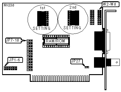
Note:The socket on the diagram labeled RAM/ROM can hold either a boot ROM chip or another 8KB RAM chip |
|||
|
CABLE TYPE |
||
|
Type |
W2 - W8 |
|
|
» |
RG-58A/U 50ohm coaxial |
2nd Setting |
|
|
AUI transceiver via DB-15 port |
1st Setting |
|
Note:Refer to the diagram for the meanings of 2nd setting & 1st setting. |
||
|
DATA BUS CONFIGURATION |
||
|
Setting |
WR27 |
|
|
» |
Any slot other than slot 8 on a PC/XT |
Open |
|
|
Slot 8 on a PC/XT |
Closed |
|
Note:If installing this card in slot 8 of a PC/XT, you must close JP27. If card is not installed in a PC/XT or |
||