XINETRON, INC.
XINET LS3251
|
Processor |
80386DX |
|
Processor Speed |
25MHz |
|
Chip Set |
C & T |
|
Max. Onboard DRAM |
16MB |
|
SRAM Cache |
None |
|
BIOS |
Award |
|
Dimensions |
355mm x 304mm |
|
I/O Options |
AUI network interface, BNC network interface, floppy drive interface, IDE interface, parallel port, serial ports (2), game port |
|
NPU Options |
80387DX |
|
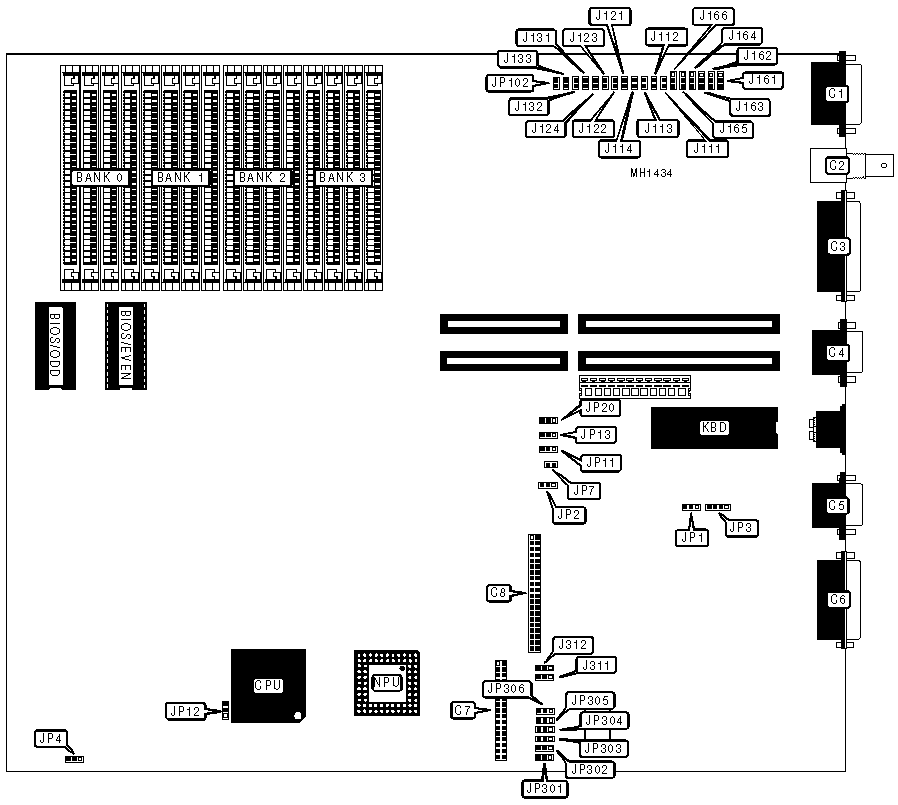
CONNECTIONS | |||
|
Purpose |
Location |
Purpose |
Location |
|
AUI ethernet interface |
C1 |
Game port |
C6 |
|
BNC ethernet interface |
C2 |
Floppy drive interface |
C7 |
|
Parallel port |
C3 |
IDE interface |
C8 |
|
Serial port (COM2) |
C4 |
Reset switch |
JP7 |
|
Serial port (COM1) |
C5 | ||
|
USER CONFIGURABLE SETTINGS | |||
|
Function |
Jumper |
Position | |
| » |
Monitor type select monochrome |
JP2 |
pins 2 & 3 closed |
|
Monitor type select color |
JP2 |
pins 1 & 2 closed | |
| » |
CPU speed select from keyboard |
JP13 |
pins 1 & 2 closed |
|
CPU speed select fast |
JP13 |
pins 2 & 3 closed | |
| » |
Floppy drive interface enabled |
JP306 |
pins 2 & 3 closed |
|
Floppy drive interface disabled |
JP306 |
pins 1 & 2 closed | |
| » |
IDE interface enabled |
J312 & J313 |
pins 2 & 3 closed |
|
IDE interface disabled |
J312 & J313 |
pins 1 & 2 closed | |
| » |
Pipeline mode enabled |
JP12 |
pins 1 & 2 closed |
|
Pipeline mode disabled |
JP12 |
pins 2 & 3 closed | |
|
SERIAL PORT CONFIGURATION | ||||
|
COM1 (C5) |
COM2 (C4) |
JP303 |
JP304 |
JP305 |
|
Enabled |
Enabled |
pins 2 & 3 closed |
pins 2 & 3 closed |
pins 2 & 3 closed |
|
Enabled |
Disabled |
pins 2 & 3 closed |
pins 1 & 2 closed |
pins 2 & 3 closed |
|
Disabled |
Enabled |
pins 1 & 2 closed |
pins 2 & 3 closed |
pins 2 & 3 closed |
|
Disabled |
Disabled |
pins 1 & 2 closed |
pins 1 & 2 closed |
pins 1 & 2 closed |
|
PARALLEL PORT (C3) CONFIGURATION | |||
|
LPT |
I/O Address |
JP301 |
JP302 |
|
LPT 1 |
3BCh |
pins 1 & 2 closed |
pins 2 & 3 closed |
|
LPT 2 |
378h |
pins 2 & 3 closed |
pins 2 & 3 closed |
|
LPT 3 |
278h |
pins 2 & 3 closed |
pins 1 & 2 closed |
|
Disabled |
N/A |
pins 1 & 2 closed |
pins 1 & 2 closed |
|
ETHERNET CABLE TYPE CONFIGURATION | |||
|
Cable Type |
JP102 |
J161-J166 | |
| » |
BNC |
Closed |
pins 1 & 2 closed |
|
AUI transceiver via 9-pin |
Open |
pins 2 & 3 closed | |
|
ETHERNET INTERRUPT REQUEST CONFIGURATION | |||||
|
Channel |
J111 |
J112 |
J113 |
J114 | |
|
IRQ 3 |
Open |
Closed |
Open |
Open | |
|
IRQ 2 |
Closed |
Open |
Open |
Open | |
|
IRQ 4 |
Open |
Open |
Closed |
Open | |
| » |
IRQ 5 |
Open |
Open |
Open |
Closed |
|
ETHERNET I/O BASE ADDRESS CONFIGURATION | |||||
|
Address |
J121 |
J122 |
J123 |
J124 | |
| » |
320h |
Open |
Closed |
Open |
Open |
|
300h |
Closed |
Open |
Open |
Open | |
|
340h |
Open |
Open |
Closed |
Open | |
|
360h |
Open |
Open |
Open |
Closed | |
|
ETHERNET BOOT ROM MEMORY ADDRESS CONFIGURATION | ||||
|
Address |
J131 |
J132 |
J133 | |
| » |
CC000h |
Open |
Closed |
Open |
|
C8000h |
Closed |
Open |
Open | |
|
D0000h |
Open |
Open |
Closed | |
|
NPU CONFIGURATION | |||
|
Mode |
JP4 |
JP11 | |
| » |
Disabled |
pins 2 & 3 closed |
pins 2 & 3 closed |
|
Asynchronous |
pins 1 & 2 closed |
pins 2 & 3 closed | |
|
Synchronous |
pins 1 & 2 closed |
pins 1 & 2 closed | |
|
DRAM CONFIGURATION | |||||
|
Size |
Bank 0 |
Bank 1 |
Bank 2 |
Bank 3 |
JP20 |
|
1MB |
(4) 256K x 9 |
NONE |
NONE |
NONE |
N/A |
|
2MB |
(4) 256K x 9 |
(4) 256K x 9 |
NONE |
NONE |
N/A |
|
4MB |
(4) 256K x 9 |
(4) 256K x 9 |
(4) 256K x 9 |
(4) 256K x 9 |
pins 1 & 2 closed |
|
4MB |
(4) 1M x 9 |
NONE |
NONE |
NONE |
N/A |
|
8MB |
(4) 1M x 9 |
(4) 1M x 9 |
NONE |
NONE |
N/A |
|
10MB |
(4) 1M x 9 |
(4) 1M x 9 |
(4) 256K x 9 |
(4) 256K x 9 |
pins 1 & 2 closed |
|
10MB |
(4) 256K x 9 |
(4) 256K x 9 |
(4) 1M x 9 |
(4) 1M x 9 |
pins 2 & 3 closed |
|
16MB |
(4) 1M x 9 |
(4) 1M x 9 |
(4) 1M x 9 |
(4) 1M x 9 |
pins 2 & 3 closed |