SEA LEVEL SYSTEMS, INC.
ACB-III
|
Card Type |
Serial card |
|
Chip Set |
Unidentified |
|
I/O Options |
Serial port |
|
Data Bus |
8-bit ISA |
|
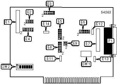
CONNECTIONS | |
|
Function |
Label |
|
Serial port |
P1 |
|
USER CONFIGURABLE SETTINGS | |||
|
Function |
Label |
Position | |
| » |
Factory configured – do not alter |
E1 |
Unidentified |
| » |
Factory configured – do not alter |
E7 |
Unidentified |
|
DMA tri state drivers permanently enabled |
E9 |
Pins 1 & 3 closed | |
|
DMA tri state drivers enabled by status control port bit 7 |
E9 |
Pins 2 & 4 closed | |
| » |
Factory configured – do not alter |
E11 |
Unidentified |
| » |
Factory configured – do not alter |
E12 |
Unidentified |
| » |
Factory configured – do not alter |
E13 |
Unidentified |
| » |
Factory configured – do not alter |
E14 |
Unidentified |
| » |
Factory configured – do not alter |
SW2 |
Unidentified |
|
SERIAL PORT 1 SELECTION | ||
|
Setting |
E6 | |
| » |
Transmit clock output (TXC out) |
Pins 1 & 2 closed |
|
Transmit clock input (TXC in) |
Pins 3 & 4 closed | |
|
Terminal timing source from SCC TRXC pin or input to TXC pin 24 on P1 |
Pins 5 & 6 closed | |
|
Terminal timing source input to RXC pins is echoed to pin 24 on P1 |
Pins 7 & 8 closed | |
|
Receive clock input |
Pins 11 & 12 closed | |
|
SERIAL PORT 2 SELECTION | ||
|
Setting |
E3 | |
| » |
Transmit clock output (TXC out) |
Pins 1 & 2 closed |
|
Transmit clock input (TXC in) |
Pins 3 & 4 closed | |
|
Terminal timing source from SCC TRXC pin or input to TXC pin 24 on P1 |
Pins 5 & 6 closed | |
|
Terminal timing source input to RXC pins is echoed to pin 24 on P1 |
Pins 7 & 8 closed | |
|
Receive clock input |
Pins 11 & 12 closed | |
|
INPUT/OUTPUT CLOCK MODE SELECTION (PORT 1) | |
|
Setting |
E10 |
|
Transmit clock output |
Pins 1 & 2 closed |
|
Transmit clock input |
Pins 3 & 4 closed |
|
Not used |
Pins 5 & 6 open |
|
Receive clock input |
Pins 7 & 8 closed |
|
INPUT/OUTPUT CLOCK MODE SELECTION (PORT 2) | |
|
Setting |
E2 |
|
Transmit clock output |
Pins 1 & 2 closed |
|
Transmit clock input |
Pins 3 & 4 closed |
|
Not used |
Pins 5 & 6 open |
|
Receive clock input |
Pins 7 & 8 closed |
|
SERIAL PORT INTERRUPT SELECTION | ||
|
IRQ |
E8 | |
|
2/9 |
Pins 1 & 2 closed | |
|
3 |
Pins 3 & 4 closed | |
|
4 |
Pins 5 & 6 closed | |
| » |
5 |
Pins 7 & 8 closed |
|
Normal IRQ mode |
Pins 9 & 10 closed | |
|
Multi IRQ mode |
Pins 11 & 12 closed | |
|
BASE I/O ADDRESS SELECTION | ||||||||
|
Setting |
SW1/1 |
SW1/2 |
SW1/3 |
SW1/4 |
SW1/5 |
SW1/6 |
SW1/7 | |
| » |
238 |
Off |
On |
On |
On |
Off |
Off |
Off |
|
280 |
Off |
On |
Off |
On |
On |
On |
On | |
|
2A0 |
Off |
On |
Off |
On |
Off |
On |
On | |
|
2E8 |
Off |
On |
Off |
Off |
Off |
On |
Off | |
|
300 |
Off |
Off |
On |
On |
On |
On |
On | |
|
328 |
Off |
Off |
On |
On |
Off |
On |
Off | |
|
3E8 |
Off |
Off |
Off |
Off |
Off |
On |
Off | |
|
DMA CHANNEL SELECTION | |
|
Channel |
E4 |
|
1 – two channel mode |
Pins 1 & 2 closed |
|
3 – two channel mode |
Pins 1 & 2 closed |
|
Two channel A/B mode A3B1 |
Pins 3 & 4 closed |
|
Two channel A/B mode A1B3 |
Pins 5 & 6 closed |
|
Closed = channel A, Open = channel B |
Pins 7 & 8 |
|
3 – acknowledges channel 3 |
Pins 9 & 10 closed |
|
1 – acknowledges channel 1 |
Pins 11 & 12 closed |
|
DMA SELECTION | |
|
Setting |
E5 |
|
SCC channel A/B uses channel 3 |
Pins 1 & 2 closed |
|
SCC channel A uses channel 3 |
Pins 3 & 4 closed |
|
SCC channel A/B uses channel 1 |
Pins 5 & 6 closed |
|
SCC channel A uses channel 1 |
Pins 7 & 8 closed |
|
SCC channel B enabled for half duplex DMA transfers |
Pins 9 & 10 closed |
|
SCC channel A – DMA channel 1/3 for full duplex transfers |
Pins 11 & 12 closed |