ARCHIVE CORPORATION
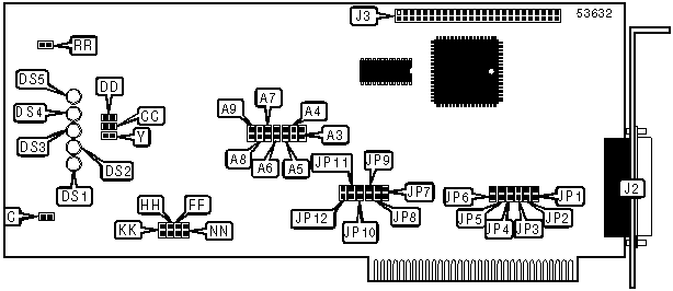
SC499
|
Card Type |
Tape drive controller |
|
Chip Set |
Unidentified |
|
Maximum Onboard Memory |
Unidentified |
|
I/O Options |
1/4 inch cartridge tape drive |
|
Tape Format |
QIC 11, QIC 24 |
|
Data Bus |
8-bit ISA |
|
Card Size |
Full-length, full-height |
|
CONNECTIONS | |||
|
Function |
Label |
Function |
Label |
|
Tape drive connector - external |
J2 |
Tape drive connector - internal |
J3 |
|
USER CONFIGURABLE SETTINGS | |||
|
Function |
Label |
Position | |
| » |
Factory configured - do not alter |
C |
Open |
| » |
Track selection - 9 |
Y |
Closed |
|
Track selection - 4 |
Y |
Open | |
| » |
Tape format - QIC-24 |
CC |
Closed |
|
Tape format - QIC-11 |
CC |
Open | |
| » |
Tape speed 90 IPS |
DD |
Open |
|
For Manufacturing test only |
DD |
Closed | |
| » |
Factory configured - do not alter |
FF |
Open |
| » |
Factory configured - do not alter |
HH |
Open |
| » |
Power-on test enabled |
KK |
Closed |
|
Power-on test disabled |
KK |
Open | |
| » |
Factory configured - do not alter |
NN |
Open |
| » |
Ready interrupt enabled |
RR |
Open |
|
Ready interrupt disabled |
RR |
Closed | |
|
DMA CHANNEL SELECTION | |||||||
|
Channel |
JP6 |
JP5 |
JP4 |
JP3 |
JP2 |
JP1 | |
| » |
1 |
Closed |
Open |
Open |
Closed |
Open |
Open |
|
2 |
Open |
Closed |
Open |
Open |
Closed |
Open | |
|
3 |
Open |
Open |
Closed |
Open |
Open |
Closed | |
|
BASE I/O ADDRESS SELECTION | ||||||||
|
Setting |
A3 |
A4 |
A5 |
A6 |
A7 |
A8 |
A9 | |
|
0h |
Off |
Off |
Off |
Off |
Off |
Off |
Off | |
|
8h |
On |
Off |
Off |
Off |
Off |
Off |
Off | |
|
10h |
Off |
On |
Off |
Off |
Off |
Off |
Off | |
|
18h |
On |
On |
Off |
Off |
Off |
Off |
Off | |
|
20h |
Off |
Off |
On |
Off |
Off |
Off |
Off | |
| » |
200h |
Off |
Off |
Off |
Off |
Off |
Off |
On |
|
3D8h |
On |
On |
Off |
On |
On |
On |
On | |
|
3E0h |
Off |
Off |
On |
On |
On |
On |
On | |
|
3E8h |
On |
Off |
On |
On |
On |
On |
On | |
|
3F0h |
Off |
On |
On |
On |
On |
On |
On | |
|
3F8h |
On |
On |
On |
On |
On |
On |
On | |
|
Note: A total of 128 base address settings are available. The jumpers are a binary representation of the decimal memory addresses. Jumper A9 is the Most Significant Bit and jumper A3 is the Least Significant Bit. The jumpers have the following decimal values: A9=512, A8=256, A7=128, A6=64, A5=32, A4=16, A3=8. Turn off the jumpers and add the values of the jumpers and convert to hexadecimal to obtain the correct memory address. (Off=0, On=1) | ||||||||
|
INTERRUPT SELECTION | |||||||
|
IRQ |
JP7 |
JP8 |
JP9 |
JP10 |
JP11 |
JP12 | |
|
IRQ2 |
Open |
Open |
Open |
Open |
Open |
Closed | |
| » |
IRQ3 |
Open |
Open |
Open |
Open |
Closed |
Open |
|
IRQ4 |
Open |
Open |
Open |
Closed |
Open |
Open | |
|
IRQ5 |
Open |
Open |
Closed |
Open |
Open |
Open | |
|
IRQ6 |
Open |
Closed |
Open |
Open |
Open |
Open | |
|
IRQ7 |
Closed |
Open |
Open |
Open |
Open |
Open | |
|
DIAGNOSTIC LED(S) |
|
Note: The function of the LEDs is unidentified, however on power up or reset all LEDs will light up. When the reset or self test is completed the LEDs will turn off. |