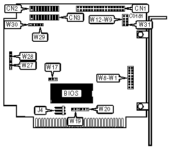
SCIENTIFIC MICRO SYSTEMS
OMTI 5520, OMTI 5527
Data bus: 8-bit, ISA
Size: Half-length, full height card
Hard drives supported: OMTI 5520:Two MFM ST506/ST412 drives
OMTI 5527:Two RLL ST506/ST412 drives
Floppy drives supported: None
Maximum heads/cyl.: 16 heads and 2048 cylinders

|
CONNECTIONS | |
|
Function |
Location |
|
34-pin control cable connector-hard drive |
CN1 |
|
20-pin data cable connector-drive 0 |
CN2 |
|
20-pin data cable connector-drive 1 |
CN3 |
|
6-pin DC power connector |
J4 |
|
USER CONFIGURABLE SETTINGS | |||
|
Function |
Location |
Setting | |
| » |
BIOS enabled |
W7 |
open |
|
BIOS disabled |
W7 |
closed | |
| » |
BIOS base address is C8000h |
W8 |
open |
|
BIOS base address is CA000h |
W8 |
closed | |
| » |
Drive 0 soft sectored |
W11 |
open |
|
Drive 0 hard sectored |
W11 |
closed | |
| » |
Drive 1 soft sectored |
W14 |
open |
|
Drive 1 hard sectored |
W14 |
closed | |
|
Not used |
WP9 | ||
|
Drive 0 is a removable drive ;drive 1 is a fixed drive (OMTI 5527 only,JP10-11 are not used on the 5520) |
W10 W11 |
closed open | |
|
Drive 0 & 1 are both hard sectored (OMTI 5527 only, JP10-11 are not used on the OMTI 5520.) |
W10 W11 |
open closed | |
| » |
Factory configured - do not alter |
W12 |
N/A |
| » |
Not documented |
W17,19,20, 27,28,29,30 |
N/A |
|
I/O PORT ADDRESS | |||
|
Address |
Jumper W5 |
Jumper W6 | |
| » |
320h |
open |
open |
|
324h |
closed |
open | |
|
328h |
open |
closed | |
|
32Ch |
closed |
closed | |
|
MISCELLANEOUS TECHNICAL NOTES |
|
W1 through W4 are used to configured the drive type as supported by the BIOS. To support most of the drives on the market, there are several different BIOS’s offered. The different BIOS drive type tables are listed with the OMTI 5510; The settings are the same for the 5520 and the 5527 |