ADVANCED STORAGE CONCEPTS
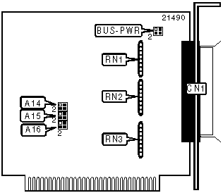
ASC-88
|
Card Type |
Hard drive controller card |
|
Hard Drives supported |
Up to 7 SCSI devices |
|
Floppy drives supported |
None |
|
Data Bus |
8-bit ISA |
|
Card Size |
Quarter-length, full-height card |

|
CONNECTIONS | |||
|
Function |
Location |
Function |
Location |
|
50-pin SCSI connector - external |
CN1 |
Terminating resistors |
RN1-RN3 |
|
USER CONFIGURABLE SETTINGS | |||
|
Function |
Location |
Setting | |
| » |
Power to external pull-ups disabled |
BUS-PWR |
Pins 1 & 2 closed |
|
+5V power to external pull-ups enabled |
BUS-PWR |
Pins 3 & 4 closed | |
|
SEGMENT ADDRESS SELECTION | |||
|
Setting |
A16 |
A15 |
A14 |
|
C000h |
Pins 1 & 2 closed |
Pins 1 & 2 closed |
Pins 1 & 2 closed |
|
C400h |
Pins 1 & 2 closed |
Pins 1 & 2 closed |
Pins 2 & 3 closed |
|
C800h |
Pins 1 & 2 closed |
Pins 2 & 3 closed |
Pins 1 & 2 closed |
|
CC00h |
Pins 1 & 2 closed |
Pins 2 & 3 closed |
Pins 2 & 3 closed |
|
D000h |
Pins 2 & 3 closed |
Pins 1 & 2 closed |
Pins 1 & 2 closed |
|
D400h |
Pins 2 & 3 closed |
Pins 1 & 2 closed |
Pins 2 & 3 closed |
|
D800h |
Pins 2 & 3 closed |
Pins 2 & 3 closed |
Pins 1 & 2 closed |
|
DC00h |
Pins 2 & 3 closed |
Pins 2 & 3 closed |
Pins 2 & 3 closed |
|
Note: A total of 8 segment address settings are available. The settings are a binary representation of the hexidecimal segment addresses. A16 is the Most Significant Bit and switch A14 is the Least Significant Bit. The jumpers have the following decimal values: A16=1000h, A15=800h, and A14=400h. Turn off the jumpers by closing pins 1 & 2 and turn on the jumpers by closing pins 2 & 3. Add the values of the jumpers with pins 2 & 3 closed to obtain the correct memory address. (Pins 1 & 2 = Off, Pins 2 & 3 = On.) | |||