COMTROL CORPORATION
HOSTESS 554 RJ45
|
Card Type |
Serial |
|
Chipset |
16554 |
|
I/O Options |
Serial ports (4) |
|
Data Bus |
16-bit ISA |
|
Card Size |
Full-height, half-length |
|
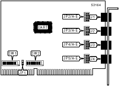
CONNECTIONS | |||
|
Function |
Label |
Function |
Label |
|
Serial port 1 |
J1 |
Serial port 3 |
J3 |
|
Serial port 2 |
J2 |
Serial port 4 |
J4 |
|
USER CONFIGURABLE SETTINGS | ||
|
Setting |
Label |
Position |
|
Interrupt mask enabled |
SW2/1 |
On |
|
Interrupt mask disabled |
SW2/1 |
Off |
|
SERIAL PORT 1 CONFIGURATION | |||||
|
Setting |
JP2/A |
JP2/B |
JP2/C |
JP2/D |
JP2/E |
|
RS-232 |
Pins 1 & 2 |
Pins 1 & 2 |
Pins 1 & 2 |
Pins 1 & 2 |
Pins 1 & 2 |
|
RS-422 |
Pins 2 & 3 |
Pins 2 & 3 |
Pins 2 & 3 |
Pins 2 & 3 |
Pins 2 & 3 |
|
Note:Pins designated are in the closed position. | |||||
|
SERIAL PORT 2 CONFIGURATION | |||||
|
Setting |
JP3/A |
JP3/B |
JP3/C |
JP3/D |
JP3/E |
|
RS-232 |
Pins 1 & 2 |
Pins 1 & 2 |
Pins 1 & 2 |
Pins 1 & 2 |
Pins 1 & 2 |
|
RS-422 |
Pins 2 & 3 |
Pins 2 & 3 |
Pins 2 & 3 |
Pins 2 & 3 |
Pins 2 & 3 |
|
Note:Pins designated are in the closed position. | |||||
|
SERIAL PORT 3 CONFIGURATION | |||||
|
Setting |
JP4/A |
JP4/B |
JP4/C |
JP4/D |
JP4/E |
|
RS-232 |
Pins 1 & 2 |
Pins 1 & 2 |
Pins 1 & 2 |
Pins 1 & 2 |
Pins 1 & 2 |
|
RS-422 |
Pins 2 & 3 |
Pins 2 & 3 |
Pins 2 & 3 |
Pins 2 & 3 |
Pins 2 & 3 |
|
Note:Pins designated are in the closed position. | |||||
|
SERIAL PORT 4 CONFIGURATION | |||||
|
Setting |
JP5/A |
JP5/B |
JP5/C |
JP5/D |
JP5/E |
|
RS-232 |
Pins 1 & 2 |
Pins 1 & 2 |
Pins 1 & 2 |
Pins 1 & 2 |
Pins 1 & 2 |
|
RS-422 |
Pins 2 & 3 |
Pins 2 & 3 |
Pins 2 & 3 |
Pins 2 & 3 |
Pins 2 & 3 |
|
Note:Pins designated are in the closed position. | |||||
|
BASE I/O ADDRESS SELECTION | |||||||||
|
Setting |
SW1/1 |
SW1/2 |
SW1/3 |
SW1/4 |
SW1/5 |
SW1/6 |
SW1/7 |
SW1/8 | |
|
0000h |
On |
On |
On |
On |
On |
On |
On |
On | |
|
0020h |
Off |
On |
On |
On |
On |
On |
On |
On | |
|
0040h |
On |
Off |
On |
On |
On |
On |
On |
On | |
|
0060h |
Off |
Off |
On |
On |
On |
On |
On |
On | |
|
0080h |
On |
On |
Off |
On |
On |
On |
On |
On | |
| » |
0280h |
On |
On |
Off |
On |
Off |
On |
On |
On |
|
1F60h |
Off |
Off |
On |
Off |
Off |
Off |
Off |
Off | |
|
1F80h |
On |
On |
Off |
Off |
Off |
Off |
Off |
Off | |
|
1FA0h |
Off |
On |
Off |
Off |
Off |
Off |
Off |
Off | |
|
1FC0h |
On |
Off |
Off |
Off |
Off |
Off |
Off |
Off | |
|
1FE0h |
Off |
Off |
Off |
Off |
Off |
Off |
Off |
Off | |
|
Note: A total of 512 base address settings are available. The switches are a binary representation of the decimal memory addresses. SW1/8 is the Most Significant Bit and switch SW1/1 is the Least Significant Bit. The switches have the following decimal values: SW1/8=4096, SW1/7=2048, SW1/6=1024, SW1/5=512, SW1/4=256, SW1/3=128, SW1/2=64, SW1/1=32. Turn off the switches and add the values of the switches that are off to obtain the correct memory address. (Off=1, On=0) | |||||||||
|
INTERRUPT SELECTION | ||||||||
|
Setting |
JP1 |
SW2/2 |
SW2/3 |
SW2/4 |
SW2/5 |
SW2/6 |
SW2/7 |
SW2/8 |
|
2 |
Pins 1 & 2 |
On |
Off |
Off |
Off |
Off |
Off |
Off |
|
3 |
Pins 1 & 2 |
Off |
On |
Off |
Off |
Off |
Off |
Off |
|
4 |
Pins 1 & 2 |
Off |
Off |
On |
Off |
Off |
Off |
Off |
|
5 |
Pins 1 & 2 |
Off |
Off |
Off |
On |
Off |
Off |
Off |
|
7 |
Pins 1 & 2 |
Off |
Off |
Off |
Off |
On |
Off |
Off |
|
10 |
Pins 1 & 2 |
Off |
Off |
Off |
Off |
Off |
On |
Off |
|
11 |
Pins 1 & 2 |
Off |
Off |
Off |
Off |
Off |
Off |
On |
|
12 |
Pins 2 & 3 |
Off |
Off |
Off |
Off |
Off |
Off |
Off |
|
Note:Pins designated are in the closed position. | ||||||||