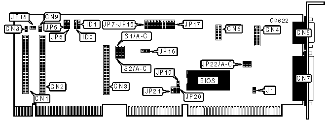
PINE TECHNOLOGY
PT-627
|
| |
|
Data bus: |
32-bit, VL-bus |
|
Size: |
Three/quarter-length, half-height card |
|
Hard drive supported: |
Four IDE (AT) interface drives |
|
Floppy drives supported: |
Two 360KB, 720KB, 1.2MB, 1.44MB, or 2.88MB drives |
|
CONNECTIONS | |
|
Function |
Location |
|
40-pin IDE (AT) interface connector - port 1 |
CN1 |
|
40-pin IDE (AT) interface connector - port 2 |
CN2 |
|
34-pin control cable connector - floppy drive |
CN3 |
|
Game port |
CN4 |
|
Serial port 1 - external |
CN5 |
|
Serial port 2 - internal |
CN6 |
|
Parallel port |
CN7 |
|
2-pin connector - primary drive port active LED |
CN8 |
|
2-pin connector - secondary drive port active LED |
CN9 |
|
USER CONFIGURABLE SETTINGS | |||
|
Function |
Location |
Setting | |
|
IOCHRDY enabled |
J1 |
Closed | |
|
IOCHRDY disabled |
J1 |
Open | |
| » |
Primary IDE port enabled |
JP5 |
Pins 1 & 2 closed |
|
Primary IDE port disabled |
JP5 |
Pins 2 & 3 closed | |
| » |
Secondary IDE port disabled |
JP6 |
Pins 2 & 3 closed |
|
Secondary IDE port enabled |
JP6 |
Pins 1 & 2 closed | |
| » |
Floppy drive enabled |
JP7 |
Pins 1 & 2 closed |
|
Floppy drive disabled |
JP7 |
Pins 2 & 3 closed | |
| » |
Game port enabled |
JP8 |
Pins 1 & 2 closed |
|
Game port disabled |
JP8 |
Pins 2 & 3 closed | |
|
ECP enabled |
JP16 |
Pins 1 & 2 closed | |
|
ECP disabled |
JP16 |
Pins 2 & 3 closed | |
|
USER CONFIGURABLE SETTINGS | ||
|
Function |
Location |
Setting |
|
CN8 and CN9 enabled for both primary and secondary IDE ports |
JP18 |
Closed |
|
CN8 used for primary IDE port/CN9 used for secondary IDE port |
JP18 |
Open |
|
PARALLEL PORT CONFIGURATION | |||
|
LPT |
JP9 |
JP11 | |
| » |
LPT2 |
Pins 1 & 2 closed |
Pins 1 & 2 closed |
|
LPT3 |
Pins 2 & 3 closed |
Pins 1 & 2 closed | |
|
Disabled |
N/A |
Pins 2 & 3 closed | |
|
ENHANCED PARALLEL PORT CONFIGURATION | |||
|
Setting |
JP10 |
JP11 | |
| » |
Standard parallel port enabled |
Pins 1 & 2 closed |
Pins 2 & 3 closed |
|
EPP enabled |
Pins 2 & 3 closed |
Pins 1 & 2 closed | |
|
ECP enabled |
Pins 1 & 2 closed |
Pins 1 & 2 closed | |
|
SERIAL PORT 1 CONFIGURATION | |||
|
COM/Address |
JP12 |
JP13 | |
| » |
COM1/3F8h |
Pins 1 & 2 closed |
Pins 1 & 2 closed |
|
COM3/3E8h |
Pins 1& 2 closed |
Pins 1 & 2 closed | |
|
Disabled |
Pins 2 & 3 closed |
N/A | |
|
SERIAL PORT 2 CONFIGURATION | |||
|
COM |
JP14 |
JP15 | |
| » |
COM2/2F8h |
Pins 1 & 2 closed |
Pins 1 & 2 closed |
|
COM4/2E8h |
Pins 2 & 3 closed |
Pins 1 & 2 closed | |
|
Disabled |
N/A |
Pins 2 & 3 closed | |
|
SERIAL PORTS 1 & 2 INTERRUPT SELECT | ||
|
IRQ |
JP20 |
JP21 |
|
IRQ3 |
Pins 2 & 3 closed |
N/A |
|
IRQ4 |
N/A |
Pins 2 & 3 closed |
|
IRQ5 |
Pins 1 & 2 closed |
N/A |
|
IRQ9 |
N/A |
Pins 1 & 2 closed |
|
HARD DRIVE SPEED | ||
|
Setting |
ID0 |
ID1 |
|
Speed 0 (HDD < 40MB) |
Pins 2 & 3 closed |
Pins 2 & 3 closed |
|
Speed 1 (40/50Mhz CPU) |
Pins 1 & 2 closed |
Pins 1 & 2 closed |
|
Speed 2 (25/33Mhz CPU) |
Pins 1 & 2 closed |
Pins 2 & 3 closed |
|
Speed 3 (<20Mhz CPU) |
Pins 2 & 3 closed |
Pins 1 & 2 closed |
|
DRQ SELECT - S1 | |||
|
DRQ |
Jumper A |
Jumper B |
Jumper C |
|
DRQ1 |
Closed |
Open |
Open |
|
DRQ3 |
Open |
Closed |
Open |
|
Disabled |
Open |
Open |
Closed |
|
DACK SELECT - S2 | |||
|
DACK |
Jumper A |
Jumper B |
Jumper C |
|
DACK1 |
Closed |
Open |
Open |
|
DACK3 |
Open |
Closed |
Open |
|
Disabled |
Open |
Open |
Closed |